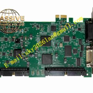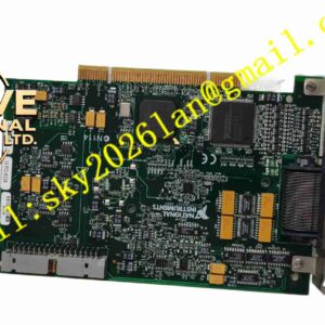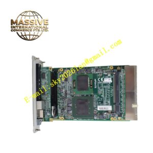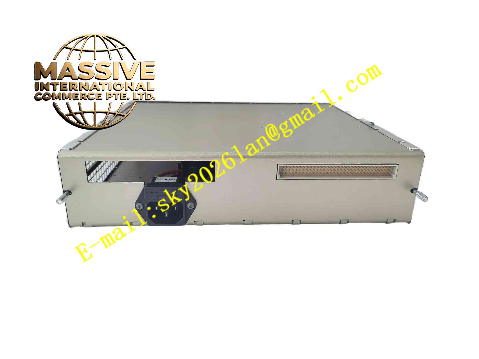
Description
NI 9505
Technical Specifications: Module type: C Series stepper motor interface module Signal output: Differential step and direction control signals Input signals: Fault feedback, home and limit switch digital inputs Backplane bus: C Series bus for CompactRIO chassis Operating temperature range: -40℃ ~ +70℃ Storage temperature range: -40℃ ~ +85℃ Relative humidity: 5% to 95%, non-condensing Connector type: Spring terminal block Form factor: C Series compact module Protection grade: IP20 inside chassis
Functional Features: Convert FPGA generated step and direction motion commands into differential control signals for external half-bridge stepper drives. Acquire digital feedback signals including home switch, positive limit, negative limit and drive fault signal. High speed digital signal transmission synchronized with FPGA real-time clock. Overvoltage and overcurrent protection for signal I/O circuit. Digital signal filtering to eliminate contact bounce and electrical noise interference. Transmit feedback status to CompactRIO FPGA for real-time motion control logic execution. Support LabVIEW FPGA programming for custom motion profile development. On-board hardware self-diagnosis for I/O circuit fault detection.
Application Scenarios: Automated laboratory positioning stages, small packaging machinery, precision material handling equipment, test probe positioning systems, semiconductor inspection motion platforms, custom automated assembly machines, miniature CNC positioning equipment.
Performance Parameters: High speed differential signal output for high frequency step pulse transmission. Fast response for limit switch and fault feedback signal capture. Continuous operation: 24 hours stable operation inside industrial control cabinet. High noise immunity differential signal reduces electromagnetic interference impact.
Material Composition: PCB substrate: Multi-layer FR4 glass fiber epoxy printed circuit board. Core components: Digital logic IC, differential line driver, signal isolation chip, surge protection diode array. Enclosure: Black flame retardant PA plastic housing. Connector: Push-in spring terminal block with gold plated copper contacts. Internal shielding: Metal shielding plate for high speed digital signal circuit.
Structural Features: Compact C Series rectangular module structure for CompactRIO chassis slot mounting. Front panel fitted with spring terminal block and signal pin marking. Internal circuit divided into backplane interface area, FPGA signal receiving area, differential signal output and feedback input area. C Series gold edge connector at module rear side for power and FPGA backplane communication. Built-in isolation circuit between external field I/O signals and internal FPGA bus.
Working Principle: NI 9505 obtains power supply from CompactRIO chassis backplane. FPGA controller sends step pulse and direction command through C Series backplane bus. On-board circuit converts these commands into differential electrical signals and outputs to external half-bridge stepper driver. Limit switch, home sensor and drive fault signals from field side enter module through spring terminals. Signal conditioning circuit filters these digital signals and transmits feedback status back to FPGA for motion logic judgment. Protection circuit suppresses transient surge from field wiring to protect internal digital circuit.
Installation Requirements: Power off CompactRIO chassis before inserting or removing NI 9505 module. Insert module into empty C Series slot and lock retaining latch. Wire stepper drive control lines and limit switch cables to spring terminals. Configure FPGA I/O mapping and motion parameters in LabVIEW FPGA project. Ensure chassis protective earth ground connection is reliable. Route low voltage control signal cables separately from high power motor cables. Reserve ventilation clearance around chassis for heat dissipation.
Usage Notes: Hot swap of module is strictly prohibited when chassis is powered on. Do not connect high voltage signals to low voltage I/O terminals. Use shielded twisted pair cable for differential step and direction signal wiring. Wear anti-static wristband during module handling and wiring. Regularly inspect terminal wiring tightness during routine maintenance. Backup FPGA project before modifying motion I/O configuration. Do not operate module outside rated environmental range.