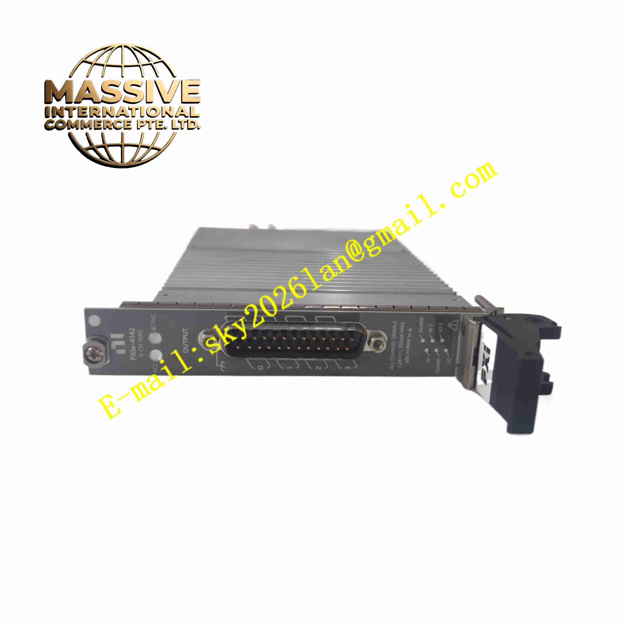
Description
NI PXIe-4142
Technical Specifications Model: PXIe-4142 Form Factor: 3U, single slot PXI Express module Channel Count: 4 independent SMU channels Voltage Range per Channel: ±24 V Current Range per Channel: ±150 mA Maximum DC Power per Channel: 3.6 W sourcing and sinking Connector: 25-pin male D-SUB front panel connector Operating Temperature: 0 ℃ ~ +55 ℃ Storage Temperature: -40 ℃ ~ +70 ℃ Relative Humidity (Operating): 10% ~ 70%, non-condensing Maximum Operating Altitude: 2000 m PXIe Power Consumption: 3.0 A @ 3.3 V, 6.0 A @12 V for 40W variant Pollution Degree: 2
Functional Features Four-quadrant operation for both power sourcing and power sinking on every channel. Four-wire remote sensing function removes cable resistance error for high precision low resistance measurement. High-speed sequencing engine synchronizes multiple SMU channels or other PXIe instruments. Independent overvoltage, overcurrent and overtemperature protection for each output channel. Simultaneous voltage and current sampling through dual synchronized ADC on each channel. Supports constant voltage mode and constant current mode with fast loop response. Programmable sampling aperture to suppress power-line frequency noise. Compatible with NI-DCPower instrument driver for programming and system integration.
Application Scenarios Semiconductor wafer probing test, LED and optoelectronic component characterization, battery and supercapacitor performance testing, MEMS sensor calibration, multi-pin integrated circuit parametric test, automotive electronic component validation.
Performance Parameters Maintains high measurement accuracy after 30 minutes of warm-up and self-calibration. Load regulation performance keeps stable output under changing DUT load conditions. Built-in protection circuit triggers shutdown immediately once overvoltage or overcurrent threshold is exceeded. High sampling rate captures transient electrical characteristics of devices under test. All channels can perform synchronous triggering without timing offset. Measurement result keeps stable under industrial electromagnetic interference environment.
Material Composition Module Housing: Black flame-retardant plastic front panel and metal shielding frame. Main PCB: FR4 multi-layer industrial printed circuit board coated with conformal protective coating. Core Electronic Components: Precision operational amplifiers, high-speed ADC and DAC chips, power output transistors, current sense resistors, isolation components, flash memory, FPGA chip. Connector: Gold-plated 25-pin D-SUB male connector and gold-plated PXIe backplane edge connector. Indicator Components: Front panel LED status indicators. Fasteners: Stainless steel screws and metal shielding brackets.
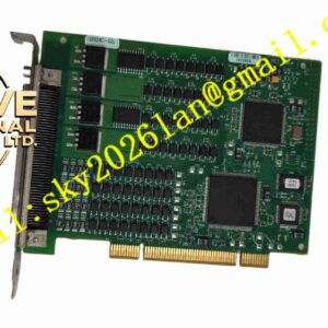
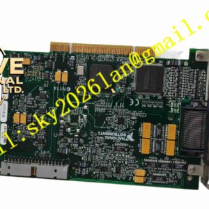
Structural Features 3U single-slot standard PXIe module mechanical structure. Front panel carries D-SUB signal connector and status LED indicators. Metal shielding shell wraps internal PCB to reduce electromagnetic radiation and interference. Rear gold-plated edge connector mates with PXIe chassis backplane for power and PXIe high-speed bus communication. Internal layout separates high power output circuit, analog measurement circuit and digital FPGA circuit. Reserved ventilation gaps for forced air cooling from PXI chassis fan.
Working Principle The module receives DC working power and PXIe bus communication signal from PXI Express chassis backplane. The onboard FPGA receives test commands from host computer through PXIe bus, and controls DAC chips to generate set voltage or current output for each channel. The output amplifier circuit drives the test signal to DUT through front panel D-SUB connector. Two synchronized high-precision ADCs collect real-time voltage and current signals from sensing circuit at the same time. The remote sense terminals feed back voltage signal directly at DUT terminals to eliminate wire voltage drop. The FPGA processes measured data and transmits measurement results back to host controller via PXIe bus. Internal monitoring circuit continuously checks voltage, current and module temperature, and cuts off channel output automatically once fault condition is detected.
Installation Requirements Power off the PXIe chassis before inserting or removing the module. Align module with empty PXIe slot, push steadily until backplane connector fully engages and front panel fasteners lock. Use shielded test cable to connect DUT to front panel D-SUB connector, follow four-wire wiring rules when using remote sensing. Install NI-DCPower driver on host computer after hardware installation. Power on chassis and complete hardware identification in NI MAX configuration software. Reserve airflow path for chassis cooling fan around module slot. Perform self-calibration after installation and before formal test execution.
Usage Precautions Do not exceed maximum voltage, current and power rating of each channel to avoid hardware damage. Use shielded cables for test wiring, single-point grounding of cable shield. Keep test cables away from high-power AC cables to reduce noise coupling. Prevent conductive dust and condensation inside PXI chassis. Do not disassemble module shielding housing without professional authorization, static sensitive components exist on PCB. Carry out regular calibration according to 1-year calibration interval requirement. Disconnect DUT and power off channel output before changing test wiring.