Description
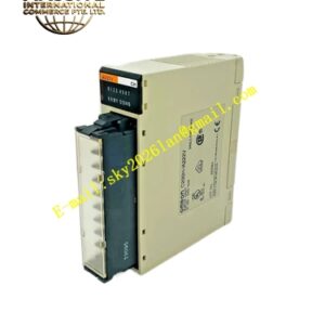
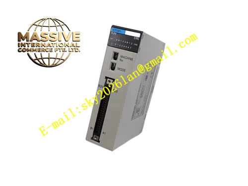
OMRON C200H‑CT021
Technical Specifications: Number of counter channels: 2 independent channels; maximum counting frequency 50 kHz; support pulse input modes: phase‑difference pulse, up‑down pulse, single‑phase pulse; count value data range ‑8 388 608 to +8 388 607; 8‑groups preset comparison values per channel; transistor comparison‑result output; input signal level compatible with DC5V and DC24V encoder signals; backplane bus power consumption 180mA at DC5V; operating temperature 0‑55°C; storage temperature ‑20‑75°C; operating humidity 10‑90%RH without condensation; rack‑slot installation; weight 280g; multiple LED indicators for channel status and comparison‑output status.
Functional Features: Two independent hardware counter channels operating free from PLC CPU scan‑cycle influence; supports multiple industry‑standard encoder pulse‑input formats; hardware‑based value comparison delivers fast response comparison‑result output; preset comparison parameters configurable via PLC programming software; channel‑status LED indicators provide direct field‑diagnostic reference; full compatibility with C200H‑series CPU backplane bus architecture.
Application Scenarios: Rotary‑encoder position‑measurement for machine‑tool axes; length‑measurement control for cutting machinery; speed‑monitoring for material‑conveying lines; high‑speed position‑trigger control for packaging equipment; spare‑part replacement for legacy C200H‑series automation installations.
Performance Parameters: Hardware‑counting response maintains stability at full‑scale 50 kHz input frequency; electrical isolation suppresses field‑side signal surge interference; meets industrial cabinet‑mount vibration and shock standards; supports continuous long‑term operation within control‑cabinet environments.
Material Composition: Black flame‑retardant engineering‑plastic housing; internal FR‑4 multilayer glass‑fiber printed‑circuit board; high‑speed counter logic processing chip; optocoupler signal‑isolation components; brass nickel‑plated external‑signal screw‑terminal block; gold‑plated backplane edge‑connector contacts; high‑brightness LED status indicators.
Structural Features: Standard C200H‑series rack‑slot physical profile; gold‑plated edge‑connector on rear housing surface for interconnection with C200H backplane bus; front‑panel screw‑terminal block for encoder pulse‑signal wiring; multiple LED status indicator groups arranged on front‑panel surface; side locking clips secure module into rack‑slot position.
Working Principle: External encoder pulse signals pass through screw‑terminal block and optocoupler isolation circuit into C200H‑CT021 internal hardware counter. Hardware counting circuit accumulates pulse numbers independent of PLC CPU scan operation. Internal comparison circuit continuously compares real‑time count value against user‑configured preset threshold values. When count value matches preset value, hardware‑level comparison‑result transistor output activates. Count value and comparison‑status data transmit to ‑series CPU via rack backplane bus for user‑program reading.
Installation Requirements: Insert ‑CT021 into any available slot on ‑series CPU main rack or expansion rack; fasten ‑series rack onto cabinet DIN rail; use shielded twisted‑pair cables for encoder pulse‑signal wiring; physically separate pulse‑signal cables from high‑power motor and inverter power cables; implement reliable protective grounding for control cabinet.
Usage Notes: Module hot‑swap operation must not be performed; confirm input‑signal voltage level matches encoder output specification; avoid exceeding maximum 50 kHz counting‑frequency limit; do not deploy within environments with condensation or corrosive gas; perform periodic inspection of screw‑terminal fastening torque.