Description
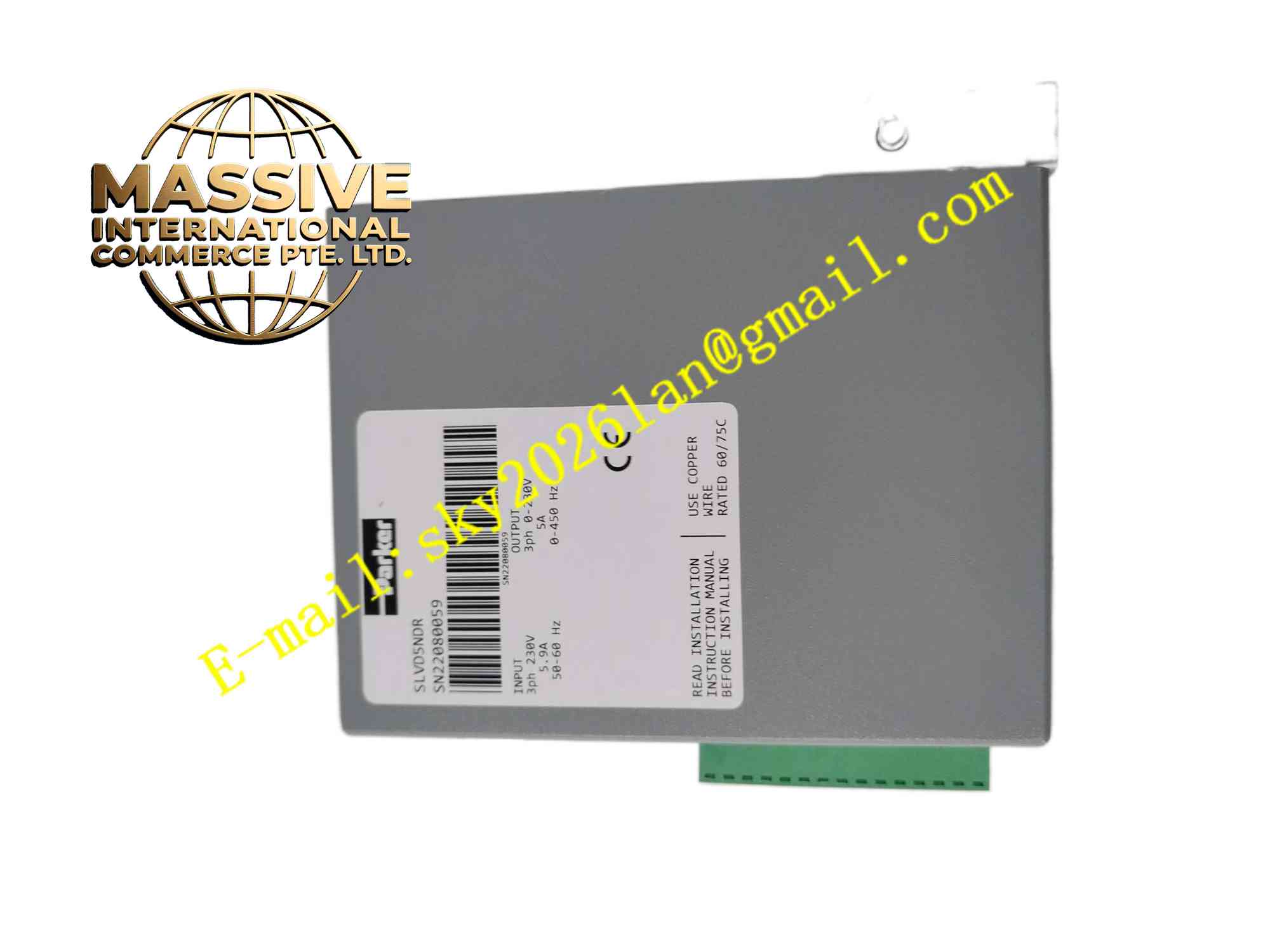
Parker SLVD5NDR
Technical Specifications Brand: Parker Model: SLVD5NDR Motor Type: Brushless permanent magnet AC servo motor Input Power: Single-phase 115 / 230 VAC Continuous Output Current: 5 A Peak Output Current: 15 A Feedback Interface: Incremental encoder differential A/B/Z signals Communication: RS232, digital I/O, pulse and direction command interface Operating Temperature: 0°C to +50°C Humidity: 5% to 90% non-condensing Protection Grade: IP20 cabinet mounting
Functional Features Supports position, speed and torque three control modes. Processes differential incremental encoder feedback signals for closed-loop position regulation. Built-in multiple safety protection functions including overcurrent, overvoltage, undervoltage, over-temperature and motor stall protection. Digital I/O terminals enable homing, enable, fault reset and status signal exchange with host controller. Pulse-direction command input accepts motion instructions from PLC or motion controller. Parameter configuration via RS232 serial port using dedicated Parker software. Integrated EMI filter reduces electromagnetic emission from power switching circuits.
Application Scenarios Packaging machinery, textile equipment, automated assembly stations, small CNC machine axes, material handling gantries, pick-and-place robotic mechanisms.
Performance Parameters Fast current loop response for rapid torque adjustment. High resolution encoder feedback processing ensures accurate positioning. Instant activation of hardware protection upon drive or motor abnormality. Low speed ripple for smooth motor rotation at low operating speeds. Stable dynamic response under frequent start-stop and position positioning cycles.
Material Composition Housing: Black flame-retardant metal casing. Power PCB: FR4 high-current multilayer printed circuit board with conformal coating. Control PCB: FR4 signal processing board. Core Components: IGBT power modules, encoder differential receivers, microprocessor, current sampling resistors, surge protection devices. Terminals: Screw clamp copper terminals for power, motor and signal wiring. Heat Sink: Aluminum alloy extrusion heat sink for power component cooling.
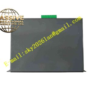
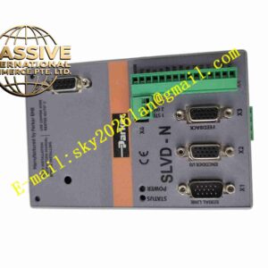
Structural Features Vertical compact rectangular metal housing. Rear aluminum heat sink dissipates heat generated by power switching devices. Front side arranged with power terminals, motor terminals and signal I/O terminal blocks. Internal layout separates high-power power circuits and low-level signal circuits to minimize crosstalk. Mounting holes on housing allow secure fixing to cabinet backplate.
Working Principle AC mains power enters the drive rectifier circuit and converts into DC bus voltage. The IGBT inverter converts DC bus power into three-phase variable frequency AC power to drive the servo motor. The encoder mounted on the motor sends rotor position and speed pulse signals back to the drive feedback circuit. The onboard microprocessor compares the command position and actual feedback position, adjusts output current in real time to realize closed-loop motion control. Protection circuits continuously monitor temperature, current and bus voltage and shut down power output immediately once hazardous operating conditions occur.
Installation Requirements Mount the servo drive vertically on a flat metal cabinet backplate. Reserve sufficient top and bottom clearance for convection cooling airflow. Use shielded motor cable and shielded encoder feedback cable. Separate power wiring and signal wiring in different cable ducts. Tighten all power terminals to specified torque rating. Connect protective earth wire reliably to cabinet ground. Set drive parameters and perform motor auto-tuning before formal operation.
Usage Notes Cut off main AC power and wait for DC bus discharge before opening drive casing. Do not exceed rated continuous and peak output current. Check heat sink temperature during continuous heavy-load operation. Avoid metal dust and conductive debris accumulation on drive surface. Verify motor wiring phase sequence before power-on test. Do not operate the drive without proper protective earth connection.