Description
PIONEER MAGNETICS PM33211BP-5-1-3-F
Technical Specifications Model: PM33211BP-5-1-3-F Input Voltage Range: 90VAC ~ 264VAC Power Factor: ≥0.95 Operating Temperature: -20℃ ~ +75℃ Storage Temperature: -40℃ ~ +85℃ Relative Humidity: 5% ~ 95% non-condensing Cooling Mode: Forced air cooling Mounting Type: Chassis screw installation Insulation Grade: Reinforced insulation EMC: Meet industrial EMC requirements
Functional Features Wide-range universal AC input, compatible with different industrial power grid specifications. Active PFC circuit improves power factor and reduces grid harmonic interference. Built-in complete protection including overvoltage protection, overcurrent protection, overtemperature protection and short-circuit protection. Power good status signal output, which feeds back the power normal signal to the external control system. Remote on-off control function supports centralized power management. Built-in EMI filter circuit to suppress conducted electromagnetic interference. High reliability proprietary magnetic components with low loss and anti-vibration capability. Support multi-module parallel operation to expand total output power.
Application Scenarios Industrial automation control cabinet, communication equipment auxiliary power supply, industrial battery charging system, factory test bench, special industrial equipment power supply, energy storage control unit power supply.
Performance Parameters High power factor under full load operating condition. The output voltage ripple is controlled within the specified range, which will not interfere with precision control circuits. The protection circuit responds rapidly under fault conditions, and automatically recovers after removing external faults. The output voltage remains stable when the input voltage and load change. Internal magnetic components have low aging rate and can run continuously for a long time.
Material Composition Outer shell: Aluminum alloy metal shell with surface anti-corrosion treatment. PCB board: Thick copper FR4 multi-layer industrial printed circuit board with conformal coating. Magnetic components: Low-loss high-frequency ferrite core and high temperature resistant enameled wire winding. Core electronic components: PFC control chip, high-frequency power switching tube, high-frequency transformer, filter capacitor, sampling and protection circuit, power status relay. Fasteners: Stainless steel anti-loosening screws. Insulating parts: Flame retardant high temperature resistant plastic and insulating film.
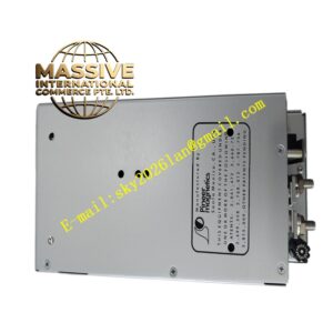
Structural Features Rectangular metal chassis structure, with mounting holes reserved at the edge of the shell for fixed installation. Internal air duct design, which guides cooling air through high heat components. High voltage circuit area and low voltage circuit area are separated by insulating baffles. Input, output and control signal terminals are arranged on the side of the shell for convenient wiring. Temperature sensors are installed near high-power components to monitor internal temperature in real time.
Working Principle The AC input enters the module and passes through the EMI filter to filter out grid interference signals. The active PFC circuit adjusts the input current waveform to improve the power factor and stabilize the high-voltage DC bus voltage. The high-frequency inverter circuit converts DC into high-frequency alternating current, and the high-frequency transformer completes voltage conversion. After rectification and filtering on the secondary side, stable DC power is output. The sampling circuit continuously collects output voltage and current signals and feeds back to the main control chip, which dynamically adjusts the switching duty cycle to stabilize the output. When the module works normally, the power good relay outputs valid signal. Once over-temperature, overvoltage, overcurrent or short circuit occurs, the control chip cuts off the power conversion circuit and changes the power status signal.
Installation Requirements Fix the module on the cabinet base plate with screws, ensure firm installation without shaking. Install cooling fan according to the air duct direction of the module. Select power cables with sufficient current-carrying capacity for input and output wiring, and tighten each terminal. Separate the routing of power cables and weak signal control cables. Complete wiring inspection and short circuit check before power-on.
Usage Precautions All wiring and maintenance operations must be carried out under power-off state. Do not block the air inlet and outlet of the cooling air channel. Regularly check the fan operation and terminal tightness in high vibration working environment. Forbid use in environments with condensation, corrosive gas and conductive dust. When multiple modules work in parallel, verify the parameter matching of each module. Use the same model for replacement when damaged; other power modules cannot be substituted without parameter verification.