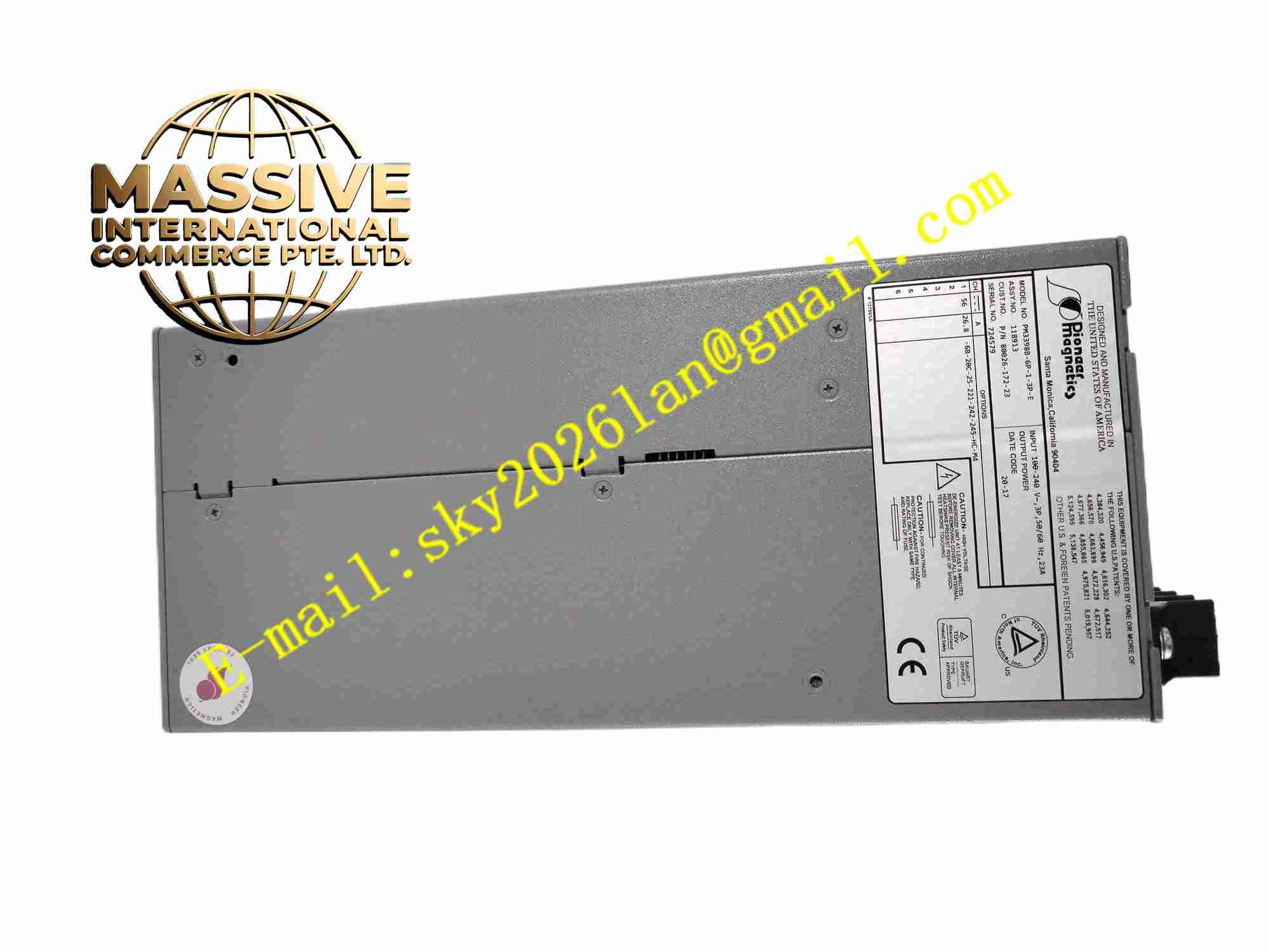
Description
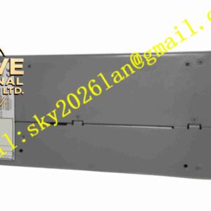
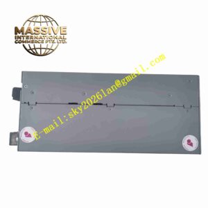
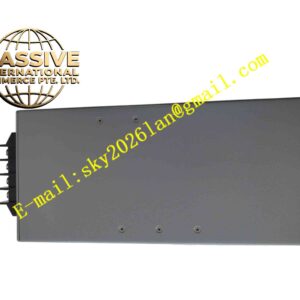
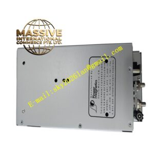
PIONEER MAGNETICS PM3398B-6P-1-3P-E 80026-172-23
Technical Specifications Model: PM3398B-6P-1-3P-E, Drawing No.80026-172-23 Input Voltage: 85VAC ~ 264VAC Power Factor: ≥0.95 Operating Temperature: -20℃ ~ +70℃ Storage Temperature: -40℃ ~ +85℃ Relative Humidity: 5% ~ 95% non-condensing Cooling Mode: Forced air cooling Parallel Function: Built-in enhanced current sharing circuit Insulation: Reinforced insulation Signal Interface: Remote enable, power good status feedback
Functional Features Enhanced built-in current sharing circuit ensures balanced load distribution when multiple modules work in parallel. Active PFC circuit improves power factor and suppresses grid harmonic current. Full protection mechanism including overvoltage, overcurrent, overtemperature and short-circuit protection. Power good relay signal output to feed back power supply operating status to upper control system. Remote on/off control terminal for centralized power management of the whole system. Built-in EMI filter to meet industrial EMC requirements. Magnetic components optimized for long-term continuous vibration working environment.
Application Scenarios Redundant power supply system of industrial control cabinet, energy storage system auxiliary power supply, large automatic production line power distribution, industrial test bench, medical industrial equipment power supply, uninterruptible power supply front-end power conversion unit.
Performance Parameters The current sharing error of parallel operation is controlled within low range, and the load is evenly distributed among multiple modules. The power factor remains stable under full load condition. The protection circuit can quickly cut off the output under fault conditions, and automatically recover after fault removal. The output voltage has low fluctuation when the input voltage and load change. The power good signal has high anti-interference performance and will not generate false triggering in industrial electromagnetic environment.
Material Composition Shell: Aluminum alloy metal shell with anti-corrosion surface treatment. PCB: Thick copper FR4 multi-layer industrial printed circuit board with conformal coating. Magnetic components: Low-loss ferrite core and high temperature resistant enameled wire winding. Core electronic components: PFC control chip, high-frequency power tube, high-frequency transformer, current sharing control circuit, filter capacitor, sampling protection circuit, status relay. Fasteners: Stainless steel anti-loosening screws. Insulating parts: Flame retardant high temperature resistant plastic and insulating film.
Structural Features Chassis metal shell structure, with mounting holes on the edge for fixed installation in cabinet. Internal air duct structure, which guides cooling air to pass through high heat components. High voltage circuit area and low voltage circuit area are separated by insulating baffles. Input, output and control signal terminals are arranged on the side of the shell. Independent current sharing signal terminal is reserved for parallel connection between multiple power modules. Temperature sensors are arranged near high-power components for real-time temperature monitoring.
Working Principle After AC input passes through EMI filter and active PFC circuit, stable high-voltage DC bus is formed. The high-frequency inverter circuit converts DC into high-frequency alternating current, which is converted by high-frequency transformer, and then rectified and filtered to obtain stable DC output. The built-in current sharing circuit collects the output current of each module connected in parallel, adjusts the output of each module in real time to realize load balance. The sampling circuit continuously monitors voltage, current and temperature signals. When the module operates normally, the power good relay outputs a valid signal. When over-temperature, overvoltage, overcurrent or short circuit occurs, the control chip cuts off the power conversion circuit and sends fault status through the power good signal.
Installation Requirements Fix the module firmly in the cabinet base plate by screws. Install the cooling fan according to the air flow direction required by the module air duct. Use cables with sufficient current capacity for input and output wiring, and tighten all terminals. When multiple modules are connected in parallel, connect the current sharing signal cables between modules as required. Power cables and weak signal control cables are routed separately. Check all wiring and short circuit before power-on.
Usage Precautions All wiring and maintenance operations must be carried out under power-off condition. Do not block the air inlet and outlet of the cooling air channel. Regularly check the fan operating state and terminal tightness in high vibration environment. Do not use in environments with condensation, corrosive gas and conductive dust. When replacing the module in parallel system, the model must be PM3398B-6P-1-3P-E with enhanced current sharing function. Do not mix ordinary PM3398B models without enhanced current sharing circuit into the parallel redundant system.