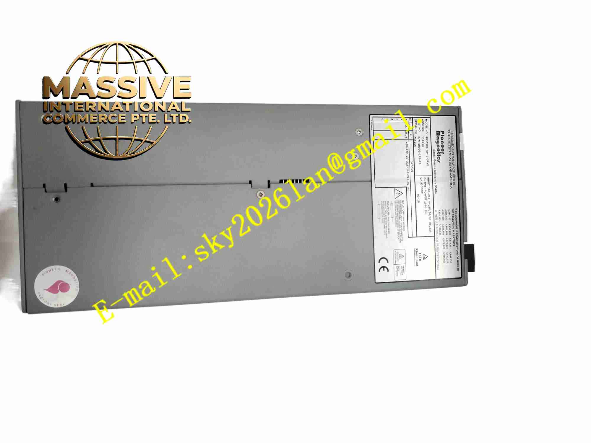
Description
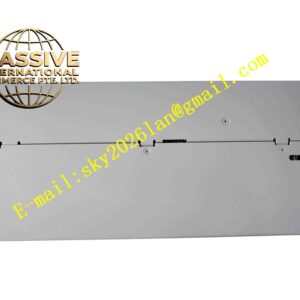
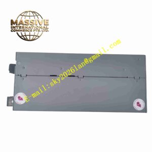
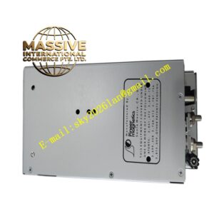
PIONEER MAGNETICS PM3398B
Technical Specifications Model: PM3398B Input Voltage Range: 85VAC ~ 264VAC Power Factor: ≥0.95 Cooling Mode: Forced air cooling Insulation Level: Reinforced insulation Operating Temperature: -20℃ ~ +70℃ Storage Temperature: -40℃ ~ +85℃ Relative Humidity: 5% ~ 95% non-condensing Mounting Method: Cabinet chassis installation EMC Compliance: Meet industrial level electromagnetic compatibility standards
Functional Features Integrated active PFC circuit to realize high power factor and reduce grid harmonic pollution. Modular platform design, different output voltage and current derivatives share the same basic hardware structure. Multi-dimensional protection functions including overvoltage, overcurrent, overtemperature and short-circuit protection. Built-in EMI filter circuit to restrain conducted interference. Support parallel redundant operation of multiple modules to improve system power supply reliability. Remote power enable/disable function and power good status signal output. High reliability magnetic components with low loss and strong anti-vibration capability.
Application Scenarios Heavy industrial control equipment, industrial battery charging systems, energy storage auxiliary power supply, factory automated production lines, special test equipment, large industrial cabinet power distribution systems.
Performance Parameters The power factor remains above 0.95 under full load working condition. The protection circuit can respond quickly when fault occurs, and the module can automatically recover after removing the external fault. The output voltage stability is high under input voltage fluctuation and load change. The internal magnetic components have strong anti-vibration performance, suitable for factory vibration environment. Long continuous running cycle meets the 24-hour uninterrupted operation requirement of industrial sites.
Material Composition Outer shell: Metal aluminum alloy shell with anti-corrosion surface treatment. PCB substrate: Thick copper FR4 industrial printed circuit board with conformal coating. Magnetic components: Low-loss ferrite core and high-temperature resistant enameled wire winding. Core electronic components: PFC control chip, high-power power tube, high-frequency transformer, electrolytic capacitor, sampling circuit, protection circuit. Fasteners: Stainless steel anti-loose screws. Insulating parts: Flame-retardant high-temperature plastic and insulating film.
Structural Features Chassis metal shell structure, reserved mounting holes for fixed installation. Internal circuit layout divides high voltage area, power conversion area and output low voltage area. Air duct structure is reserved inside the shell to cooperate with forced air cooling heat dissipation. Input and output terminals are arranged on the side of the shell for convenient wiring operation. Built-in temperature sensing element, which collects internal temperature of the module in real time.
Working Principle The AC input passes through the EMI filter, enters the active PFC correction circuit to adjust the power factor and stabilize the DC bus voltage. The high-voltage DC bus supplies power to the high-frequency inverter circuit, which drives the high-frequency transformer for voltage transformation. The secondary side obtains the required DC voltage after rectification and filtering. The sampling circuit collects the output voltage and current signals and feeds back to the main control chip to dynamically adjust the switching pulse width and maintain stable output. When the internal temperature exceeds the threshold or the load is short-circuited, the protection circuit cuts off the power conversion circuit to avoid component damage.
Installation Requirements Fix the module firmly in the industrial cabinet through the reserved mounting holes. Arrange the air duct to ensure that the cooling air flows through the heat-generating components inside the module smoothly. The input and output cables must match the rated current, and the terminals must be tightened. High-voltage power cables and weak signal control cables are routed separately. Complete wiring inspection before power-on to avoid short circuit and wrong connection.
Usage Precautions Power off the whole system before disassembly and wiring. Do not block the air inlet and outlet, otherwise it will trigger overtemperature protection. Regularly check the aging of capacitors and fan operation status during long-term operation. The module cannot work in the environment with condensation and corrosive gas. When multiple modules are used in parallel, the parameters must be matched to realize balanced current sharing.