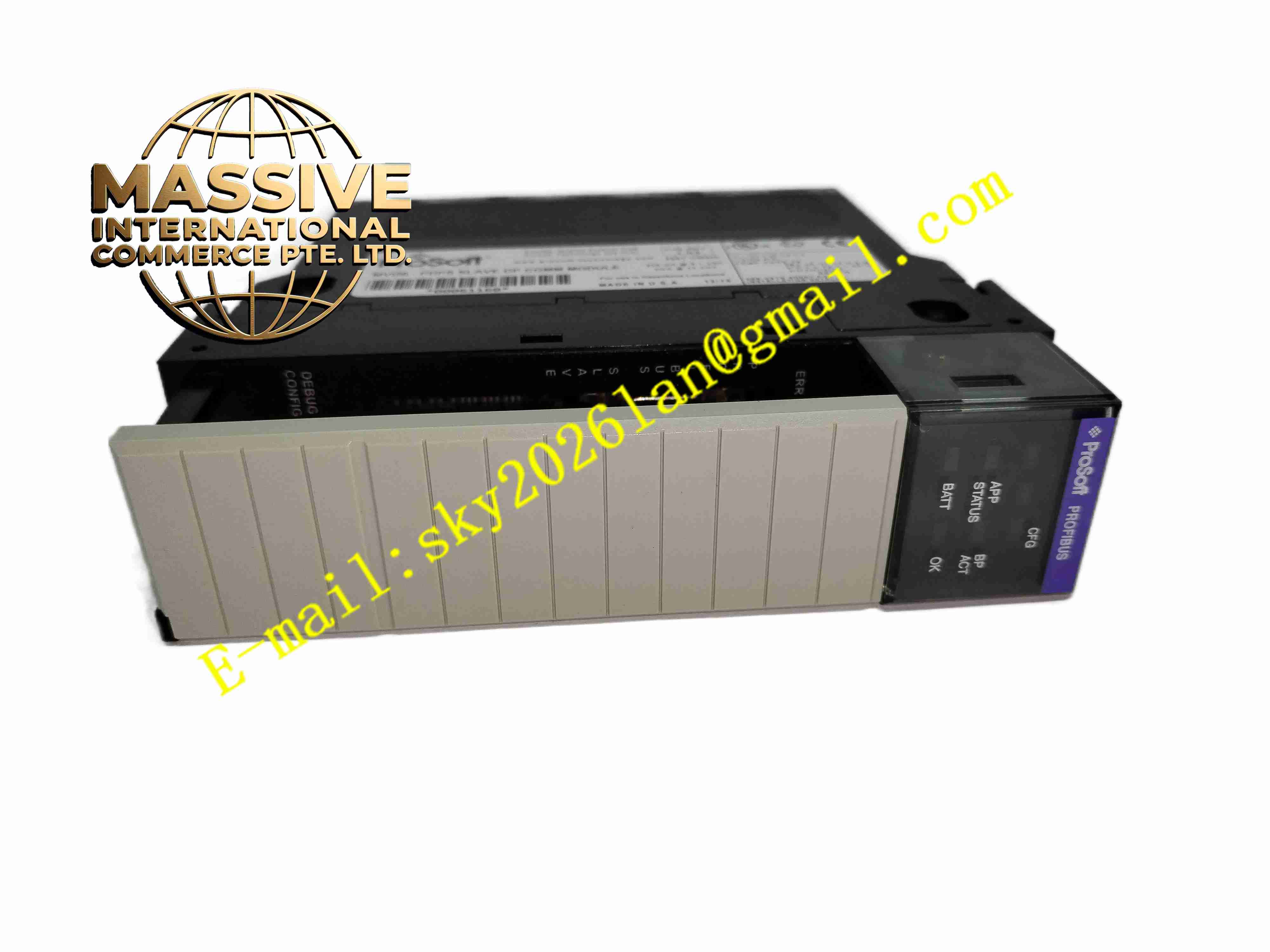
Description
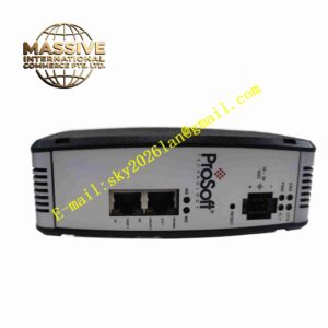
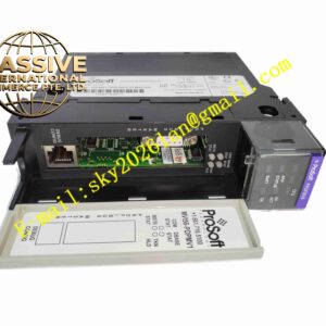
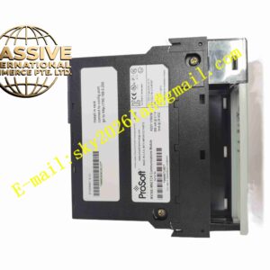
ProSoft MVI56-PDPS
Technical Specifications: Chassis compatibility: Rockwell 1756 ControlLogix single slot Backplane bus: ControlLogix backplane bus PROFIBUS interface: 9-pin D-sub female PROFIBUS DP connector Operating supply voltage: 5V DC supplied from chassis backplane Operating temperature range: 0℃ ~ +60℃ Storage temperature range: -40℃ ~ +85℃ Relative humidity: 5% to 95%, non-condensing Communication protocol: PROFIBUS DP-V0 Slave Configuration software: ProSoft Configuration Builder Protection grade: IP20 Vibration standard: Compliant with IEC60068-2-6 industrial vibration test standard
Functional Features: Work as PROFIBUS DP slave station responding to read and write commands issued by PROFIBUS DP master. Complete cyclic I/O data transmission between PROFIBUS master and ControlLogix controller. Support user configurable bidirectional data mapping between PROFIBUS bus and ControlLogix tag memory area. Real-time monitoring of PROFIBUS bus communication status and record communication fault events. On-board LED indicators to display module power, bus communication and fault alarm status. Store configuration parameters in non-volatile memory and retain data after power loss. Support Add-On Instruction integration for seamless programming inside RSLogix 5000 environment.
Application Scenarios: Petrochemical plant PROFIBUS network integration projects, metallurgical production line control cabinet retrofitting, paper mill process automation, water treatment fieldbus control system, cement factory automation, legacy PROFIBUS system upgrade mixed with Rockwell ControlLogix controllers.
Performance Parameters: Support all standard PROFIBUS DP baud rate options. Cyclic data synchronously transmitted through ControlLogix backplane I/O channel. Real-time capture of bus interruption, communication timeout and parity error. Continuous running capacity: 24 hours uninterrupted long-term operation inside industrial control cabinet. Data mapping capacity: Configurable input and output data length for PROFIBUS cyclic exchange.
Material Composition: Circuit substrate: FR4 high temperature resistant glass fiber epoxy printed circuit board. Core electronic components: Industrial communication processor, PROFIBUS protocol chip, non-volatile memory chip, isolation optocoupler. Front panel: Black flame retardant ABS plastic with silk screen text and LED windows. Backplane connector: Gold plated copper alloy contact pins with anti-oxidation treatment. PROFIBUS D-sub connector: Metal shell with PA66 flame retardant plastic internal insulation.
Structural Features: Standard single-slot rectangular plug-in board structure matching 1756 ControlLogix chassis. Front panel equipped with 9 pin D-sub PROFIBUS port and multiple LED status indicators. Internal circuit layout divided into backplane power supply area, PROFIBUS protocol processing area and data storage area. Built-in mechanical locking latch to fix module firmly in chassis slot. Internal signal isolation circuit to suppress electromagnetic noise from PROFIBUS field cable.
Working Principle: The module receives 5V DC working power through ControlLogix chassis backplane. It acts as PROFIBUS DP slave device on PROFIBUS fieldbus. When PROFIBUS master sends cyclic read or write request, the module receives bus signal, completes protocol parsing, exchanges data with ControlLogix controller via backplane bus, and returns response data back to PROFIBUS master. The module continuously monitors bus signal quality. When communication error occurs, it triggers fault flag and records fault information into on-board memory. All user-defined mapping parameters are saved in non-volatile memory and loaded automatically after power restart.
Installation Requirements: Cut off the power supply of ControlLogix chassis before inserting or removing module. Insert MVI56-PDPS module into empty single slot of 1756 chassis and lock mechanical latch. Connect standard PROFIBUS shielded twisted pair cable to 9 pin D-sub connector. Install matching terminal resistor at both ends of PROFIBUS bus cable. Configure data mapping table and PROFIBUS station address by ProSoft Configuration Builder software. Ensure control cabinet protective earth ground is reliably connected. Leave sufficient air gap between adjacent modules for heat dissipation.
Usage Notes: Hot swap operation is forbidden when chassis backplane is energized. Backup module configuration file before parameter modification or firmware upgrade. Use PROFIBUS certified shielded twisted pair cable for field wiring. Regularly inspect D-sub connector tightness and LED indicator status during maintenance. Wear anti-static wristband when touching circuit board to prevent static damage. Do not expose module to environment beyond rated temperature and humidity range. Prevent metal debris, conductive dust and liquid from entering module circuit region.