Description
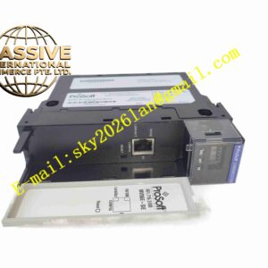
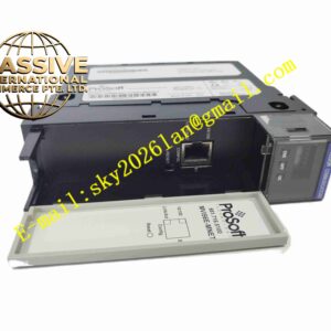
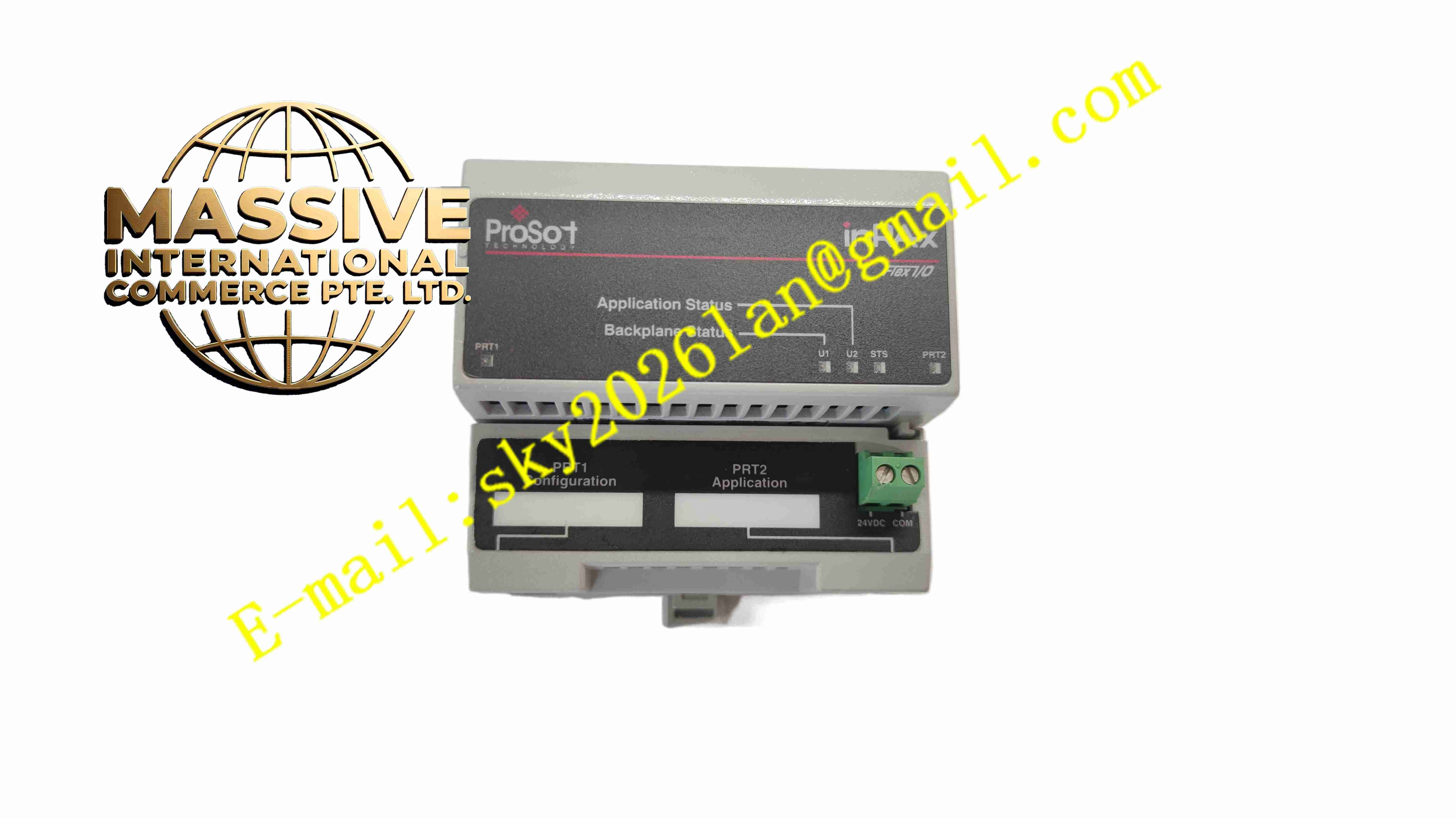
ProSoft MVI94-MCM-MHI
Technical Specifications: Platform compatibility: Rockwell Flex I/O backplane Backplane current consumption: 800mA at 5V DC Serial ports: Dual configurable RJ45 serial ports, convert to DB9 via adapter cable Operating temperature range: 0℃ ~ +60℃ Storage temperature range: -40℃ ~ +85℃ Relative humidity: 5% to 95%, non-condensing Protocol: Modbus RTU, Modbus ASCII, Enron Modbus Maximum register database: 5000 16-bit register words Shock resistance: 30g during operation, 50g non-operational Vibration resistance: 5g within frequency range from 10Hz to 150Hz Protection grade: IP20
Functional Features: Dual serial ports independently configurable as Modbus master or Modbus slave. Modbus master function supports up to 100 polling commands on each serial port. Built-in optimized polling logic to reduce polling frequency for offline faulty slave devices. Support Enron Modbus protocol for floating-point data reading and writing. Bidirectional data exchange between Modbus register database and Flex controller data files. Debug port for local parameter configuration and real-time communication diagnosis. On-board LED indicators for module status, serial port activity and fault alarm. Store user configuration in non-volatile memory and retain data after power loss.
Application Scenarios: Distributed field I/O stations, water treatment remote instrument collection, oil and gas well site monitoring, food and beverage production line, building energy monitoring, conveyor automation system, Modbus instrument integration for Flex I/O control system.
Performance Parameters: Serial baud rate: Multiple standard baud rate options for Modbus serial communication. Data refresh: Asynchronous data transfer between Modbus network and Flex backplane I/O image. Diagnostic performance: Real-time capture serial frame error, timeout and parity error. Continuous operation: 24 hours stable continuous operation in field I/O cabinet environment. Data storage capacity: Up to 5000 register words for Modbus data buffer.
Material Composition: PCB substrate: FR4 glass fiber epoxy industrial printed circuit board. Core chips: Industrial communication processor, serial transceiver chip, non-volatile memory chip. Module housing: Black flame retardant PA plastic shell with integrated Flex base latch. RJ45 connectors: PA66 flame retardant plastic housing with gold-plated contact pins. Solder: Lead-free industrial tin solder.
Structural Features: Modular structure matched with Flex I/O base unit, easy snap-on installation. Two RJ45 serial ports and debug port arranged on module front panel. Multiple LED indicator lights on front panel to show power, port transmit/receive and fault state. Internal circuit partition: backplane interface circuit, dual serial communication circuit and memory storage circuit. Built-in mechanical latch to lock module onto Flex I/O base. Circuit isolation design to reduce serial port surge interference.
Working Principle: The module obtains power from Flex I/O backplane after installation. When configured as Modbus master, it actively sends read and write commands to Modbus slave devices on serial bus. When configured as Modbus slave, it responds to read and write requests sent by external Modbus master. All exchanged Modbus data is stored in internal register database. The module synchronizes data between internal database and Flex controller data area through Flex backplane bus. The debug port outputs real-time communication log and fault information for maintenance debugging.
Installation Requirements: Power off Flex I/O rack before installing or removing module. Mount module onto Flex I/O base and lock the mechanical latch. Connect RJ45 to DB9 adapter cable to module serial port for field Modbus wiring. Set serial port parameters, master command list and register mapping through configuration file. Ensure Flex rack protective earth ground connection is reliable. Keep enough clearance around module for natural air cooling.
Usage Notes: Cut off rack power before module disassembly. Backup configuration file before modifying serial communication parameters. Use shielded twisted pair cable for long-distance Modbus serial wiring. Check serial cable shielding and terminal resistance regularly during routine maintenance. Wear anti-static wristband during module handling and maintenance. Do not operate module outside rated temperature and humidity range.