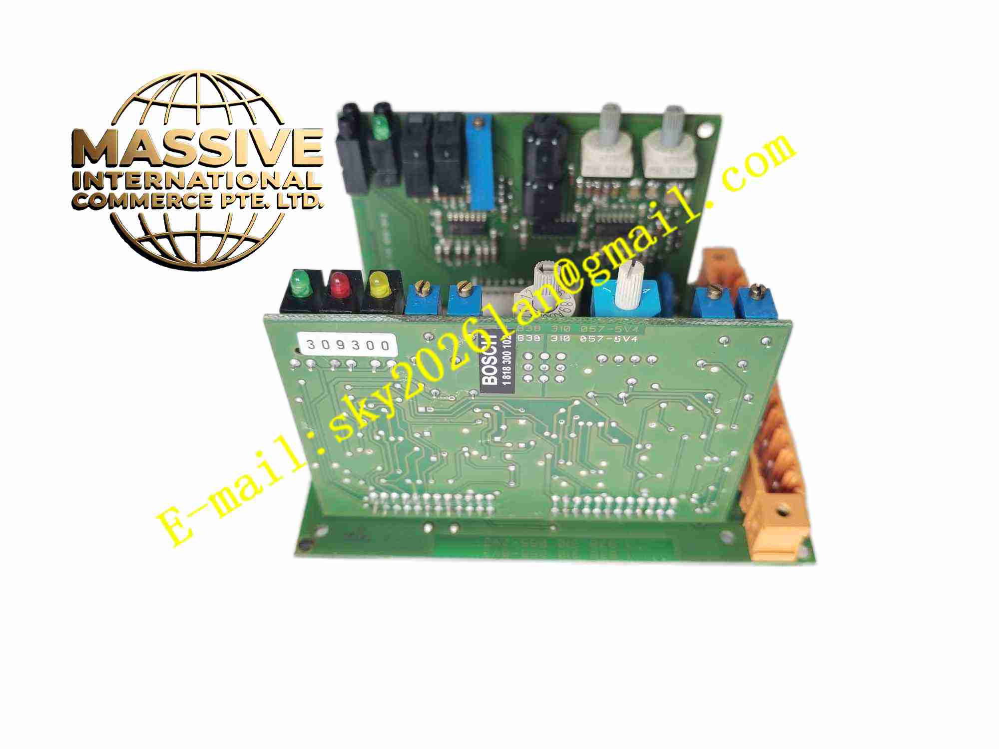
Description
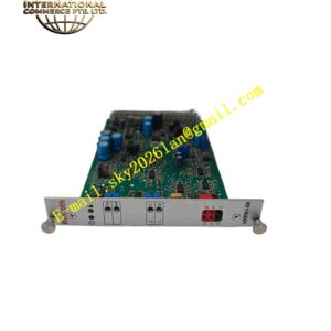
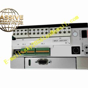
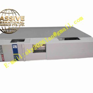
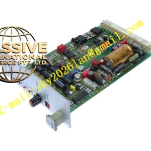
Rexroth VT-MACAS-500-10V0I
Technical Specifications
Manufacturer: Bosch Rexroth
Product family: VT-MACAS analog controller
Product type: analog position controller for valves with integrated electronics
Order reference: 0811405140 for VT-MACAS-500-10/V0/I
Control mode: PT1 position control, PI velocity control with tachometer
Setpoint input: ±10 V differential voltage input and 4-20 mA current input
Actual value input: ±10 V differential voltage and 4-20 mA depending on configuration
Valve output: compatible with valves having integrated electronic control
Power supply: 24 V DC typical, with acceptable supply range depending on variant
Mounting: DIN rail module or European card format 100 mm × 160 mm
Diagnostic features: actual-value cable break detection and short-circuit protected interfaces
Configuration: front-panel test points and parameter adjustment
Protection: reverse polarity protection and interface short-circuit protection
Operating environment: industrial control cabinet installation
Functional Features
Analog closed-loop position control
Velocity control with tachometer feedback
Ramp generator for smooth acceleration and deceleration
Dead-band compensation
Cable break monitoring for actual-value signal
Short-circuit protected interfaces
Reverse polarity protection
Front-panel test points for diagnostics
Parameter adjustment via front-panel controls
Suitable for valves with integrated electronics
Application Scenarios
Hydraulic cylinder position control
Industrial press hydraulic systems
Injection molding machine axes
Metal forming equipment
Material handling hydraulic actuators
Test equipment position regulation
Machine tool hydraulic circuits
Automation systems with analog valve control
Retrofit of analog hydraulic control loops
General industrial hydraulic position regulation
Performance Parameters
Control type: analog closed-loop position/velocity control
Position control: PT1 control characteristic
Velocity control: PI control characteristic with tachometer
Setpoint range: ±10 V and 4-20 mA
Actual value range: ±10 V and 4-20 mA depending on configuration
Ramp function: adjustable acceleration and deceleration
Diagnostics: cable break detection and fault signaling
Protection: short-circuit and reverse polarity protection
Reliability: industrial analog controller design
Service life: dependent on operating environment and hydraulic system condition
Material Composition
Printed circuit board assembly
Analog signal conditioning circuits
Microcontroller-based control electronics
Terminal block and connector interface
Front-panel adjustment elements
LED status indicators
Test point terminals
Protective housing or card frame
Grounding and shielding hardware
Identification label with VT-MACAS-500-10/V0/I designation
Structural Features
Modular DIN rail or European card format design
Front-panel test points for commissioning
Adjustment elements for zero, gain, and ramp settings
LED indicators for status and fault
Terminal connections for setpoint, feedback, and valve signals
Compact industrial controller layout
Robust mechanical construction
Clear model identification
Designed for cabinet or rack installation
Easy replacement and maintenance access
Working Principle
The VT-MACAS-500-10/V0/I receives an analog setpoint signal representing the desired cylinder position or velocity. It compares this setpoint with the actual position feedback from a potentiometer, LVDT, or other analog sensor. The controller adjusts the output signal to the valve with integrated electronics until the actual position matches the commanded value. Ramp generation limits acceleration and deceleration to reduce hydraulic shock. Cable break detection and fault monitoring help identify sensor or wiring problems.
Installation Requirements
Install in a dry and clean control cabinet
Mount the module securely on a DIN rail or in a compatible card frame
Connect the correct 24 V DC supply voltage
Wire setpoint, feedback, and valve signals according to the wiring diagram
Verify sensor type and signal range before commissioning
Check cable integrity for feedback and setpoint lines
Configure ramp time, zero, and gain settings before operation
Ground the system properly to reduce electrical interference
Usage Precautions
Do not exceed the rated supply voltage
Verify that the connected valve supports integrated electronic control
Check feedback sensor wiring before enabling control
Avoid mechanical shock to sensors and connectors
Test cable break detection during commissioning
Keep the module protected from moisture and conductive dust
Replace only with genuine Rexroth parts or approved equivalents
Refer to the official Bosch Rexroth VT-MACAS documentation for final wiring, configuration, and safety limits