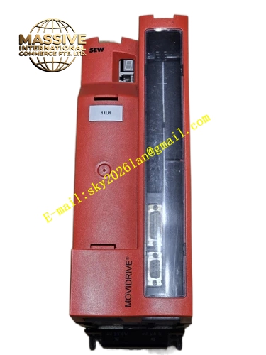
Description
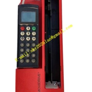
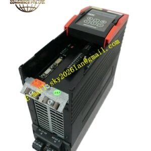
SEW MDX61B0022-5A3-4-00
Technical Specifications: Rated motor power:2.2kW Three-phase input voltage:380VAC–500VAC Control modes: VFC open-loop flux control, CFC closed-loop current flux vector control Built-in brake chopper, four-quadrant operation Protection class:IP20 Ambient operating temperature:0℃ to +45℃ Cooling method:Forced air cooling
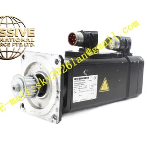
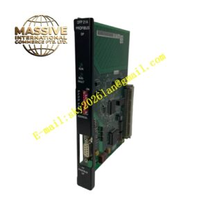
Functional Features: Modular split design with pluggable front control card Vertical DIN rail or screw installation inside closed electrical cabinet IP20 protection grade for cabinet internal use Full hardware protection including overcurrent, overvoltage, undervoltage, overtemperature, earth fault, short circuit and encoder fault Closed-loop driving for SEW synchronous servo motors Multi-channel digital and analog I/O terminals Automatic motor parameter identification Parameter backup and restore function Optional PROFIBUS-DP, EtherCAT, PROFINET communication cards Built-in positioning, electronic cam and master-slave synchronization functions Integrated STO Safe Torque Off safety function
Application Scenarios: Packaging machine servo axis Cutting machine positioning servo drive Printing auxiliary roller synchronization Automated handling sliding table axis Indexing rotary table servo control
Performance Parameters: Output frequency range:0Hz–600Hz Overload capacity:150% rated current for 60 continuous seconds Speed control accuracy ±0.01% under CFC closed-loop mode Independent adjustable acceleration and deceleration ramps Torque limit and pure torque control mode High-speed encoder signal acquisition and processing
Material Composition: Cold rolled steel sheet housing with powder coating anti-corrosion treatment Multi-layer industrial PCB pluggable control card IGBT inverter power module NTC temperature monitoring sensor Gold-plated signal terminals, copper high-current power terminals Flame-retardant plastic insulating brackets High-voltage DC bus electrolytic capacitors Small metal heat sink and cooling fan
Structural Characteristics: Vertical modular cabinet mounting structure with rear DIN rail buckles and screw holes Pluggable control card on front panel for easy maintenance Front LED indicators showing running, fault and bus communication state Upper main circuit power terminals, lower control signal terminals Side expansion slots reserved for communication option card installation Power cavity and signal cavity physically separated to suppress electromagnetic interference
Working Principle: Three-phase AC power is rectified into DC bus voltage in power unit. IGBT power module converts DC voltage to variable voltage variable frequency three-phase AC to drive synchronous servo motor. Encoder continuously collects rotor speed and position information and transmits feedback signal to pluggable control card. CFC closed-loop vector algorithm calculates motor flux and torque in real time and dynamically adjusts output voltage and frequency to realize high precision speed, torque and position control. Regenerative energy during deceleration passes built-in brake chopper and dissipates on external brake resistor. Fault will trigger hardware shutdown and store fault log inside control card.
Installation Requirements: Vertical upright installation inside closed electrical cabinet, inverted or horizontal installation forbidden Reserve enough ventilation space and do not block cooling fan air channel Power cables and signal cables must be routed separately, signal cables adopt shielded cables Three-phase input voltage must match nameplate rating Installation environment excludes dust, corrosive gas and condensed water vapor PE protective earth terminal must be fastened firmly Encoder cable uses SEW designated shielded cable
Precautions for Use: Wait at least 10 minutes after power-off for capacitor full discharge before opening cover or replacing control card Check input power voltage before power-on Complete full motor identification during commissioning Capacitors and surge absorbers cannot be connected in parallel on output terminals Clean cooling fan and heat sink dust regularly ESD anti-static protection must be used when plugging control card and communication cards External brake resistor must match specification, short-circuit of brake terminals prohibited STO safety circuit wiring strictly complies with official safety manual