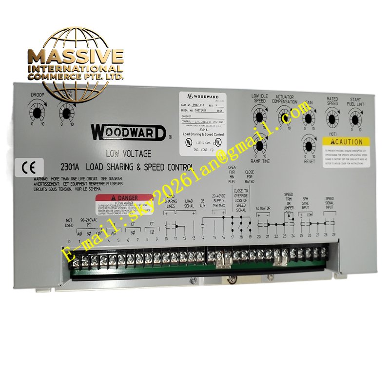
Description
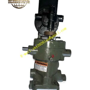
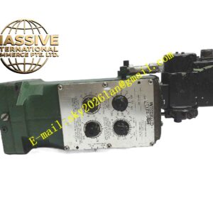
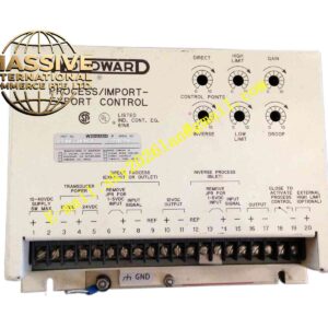
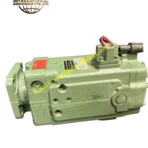
Woodward 2301A 9907-018
Technical Specifications Dual magnetic pickup speed sensor inputs; analog actuator drive output; load sharing communication interface; adjustable speed droop and gain parameters; configurable start fuel and ramp limits; 24V DC control power supply.
Functional Features Maintains prime mover rotational speed at the user defined setpoint. Distributes electrical load evenly across multiple paralleled generator units. Provides speed ramp control during generator startup and shutdown. Supports isochronous and droop control operating modes. Monitors speed sensor health and triggers alarm for signal loss.
Application Scenarios Diesel generator sets, gas engine generators and small steam turbines deployed in island power plants, backup standby power systems and remote site power generation facilities.
Performance Parameters High speed regulation accuracy; fast response to load step changes; stable load balance between parallel generators; configurable dynamic response parameters for different engine characteristics.
Material Composition Controller housing is coated aluminum alloy; internal PCB is FR‑4 flame retardant multilayer board; signal and power terminals are nickel plated copper; internal processing chips are industrial wide temperature components; front panel membrane overlay is wear resistant polyester film.
Structural Characteristics Rack mount metal enclosure; front panel with adjustment potentiometers, status indicator LEDs and configuration switches; rear terminal blocks for speed sensors, actuator drive, power supply and load sharing wiring.
Working Principle Magnetic pickup sensors generate frequency signals proportional to shaft rotational speed. The controller converts frequency to measured speed value and calculates error between actual speed and reference speed. The control algorithm outputs a drive signal to the fuel actuator to adjust fuel supply. For parallel generators, the controller exchanges load data with other 2301A units to balance power output.
Installation Requirements Mount the controller inside a vibration protected control cabinet. Route magnetic pickup shielded cable separately from high current wiring. Wire actuator output to the fuel control actuator per schematic. Complete speed calibration, gain tuning and load sharing setup after power up.
Precautions for Use Magnetic pickup wiring must use shielded cable with single point grounding. Do not alter internal circuit components. Retain all tuning parameter records after commissioning. Verify overspeed protection circuits independently from the governor controller.