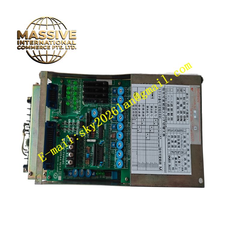
Description
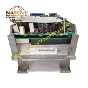
Yaskawa CACR-SR20TB0BM
Technical Specifications Three-phase 200V AC input power. Rated output capacity 2.0kW. Support incremental encoder feedback. Built-in pulse command and serial communication interfaces. Analog reference signal input. Built-in dynamic brake circuit. Multiple hardware fault protection functions. Operating ambient temperature 0°C to 55°C. IP20 protection rating. Support external regenerative resistor connection.
Functional Features Process digital pulse commands and analog speed/torque signals from host controllers. Adopt encoder feedback to form high-precision closed-loop motion control. Support external regenerative resistor connection to consume regenerative energy during motor deceleration. Record alarm information, operating current and running time in internal memory. Allow gain adjustment, electronic gear setting and alarm reset through local panel or upper software. Output fault relay signals to notify the host system of abnormal states.
Application Scenarios Large gantry automation equipment, heavy-duty material handling machinery, metal cutting auxiliary axes, palletizing equipment, large forming machine servo axes.
Performance Parameters High peak torque output capacity. Strong load impact resistance. Stable bus voltage control during high-speed deceleration. High anti-interference performance in industrial power environments. Adjustable notch filter for mechanical resonance suppression.
Material Composition Main power board uses thick copper FR-4 flame-retardant substrate. Power switching elements are high-power IGBT modules. Control board is multilayer FR-4 printed circuit board. Heat sink is cast aluminum alloy. Shell is painted steel plate. Wiring terminal contacts adopt nickel-plated copper alloy. Internal energy storage components are high-voltage electrolytic capacitors.
Structural Characteristics Vertical cabinet installation structure with larger heat sink area compared with low-power models. Front panel contains digital display, function buttons and status LEDs. Rear and bottom areas arrange power terminals, motor terminals and signal terminals separately. Internal air duct design guides cooling air through power semiconductor heat sink. Side fixing lugs are used for fastening inside electrical cabinets.
Working Principle Three-phase AC power is rectified into DC bus voltage. The inverter module outputs PWM AC power to the servo motor. Encoder signals transmit rotor position to the control core for closed-loop calculation. When the motor decelerates, regenerative energy feeds back to the DC bus, and the energy is consumed by the built-in or external regenerative resistor. The monitoring circuit samples electrical parameters in real time and executes protection when overcurrent, overvoltage or overheating occurs.
Installation Requirements Install the unit vertically in a well-ventilated control cabinet. Connect three-phase AC power supply, motor power cable, encoder cable and regenerative resistor wiring to designated terminals. Complete motor parameter setting and loop gain optimization via operation panel. Perform no-load test and load trial operation sequentially. Ensure the grounding wire meets industrial grounding specifications.
Precautions for Use The regenerative resistor will generate high temperature during operation and must maintain isolation from combustible materials. Shielded cables must be adopted for encoder signals and single-point grounding is required. Do not operate the drive beyond the rated current and voltage range. Clean dust on heat sink and fan regularly. Discharge the internal capacitors completely before maintenance work.