Description
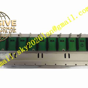
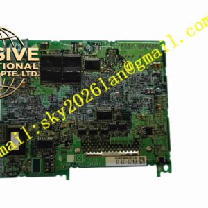
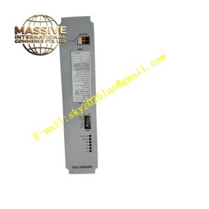
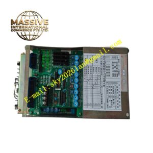
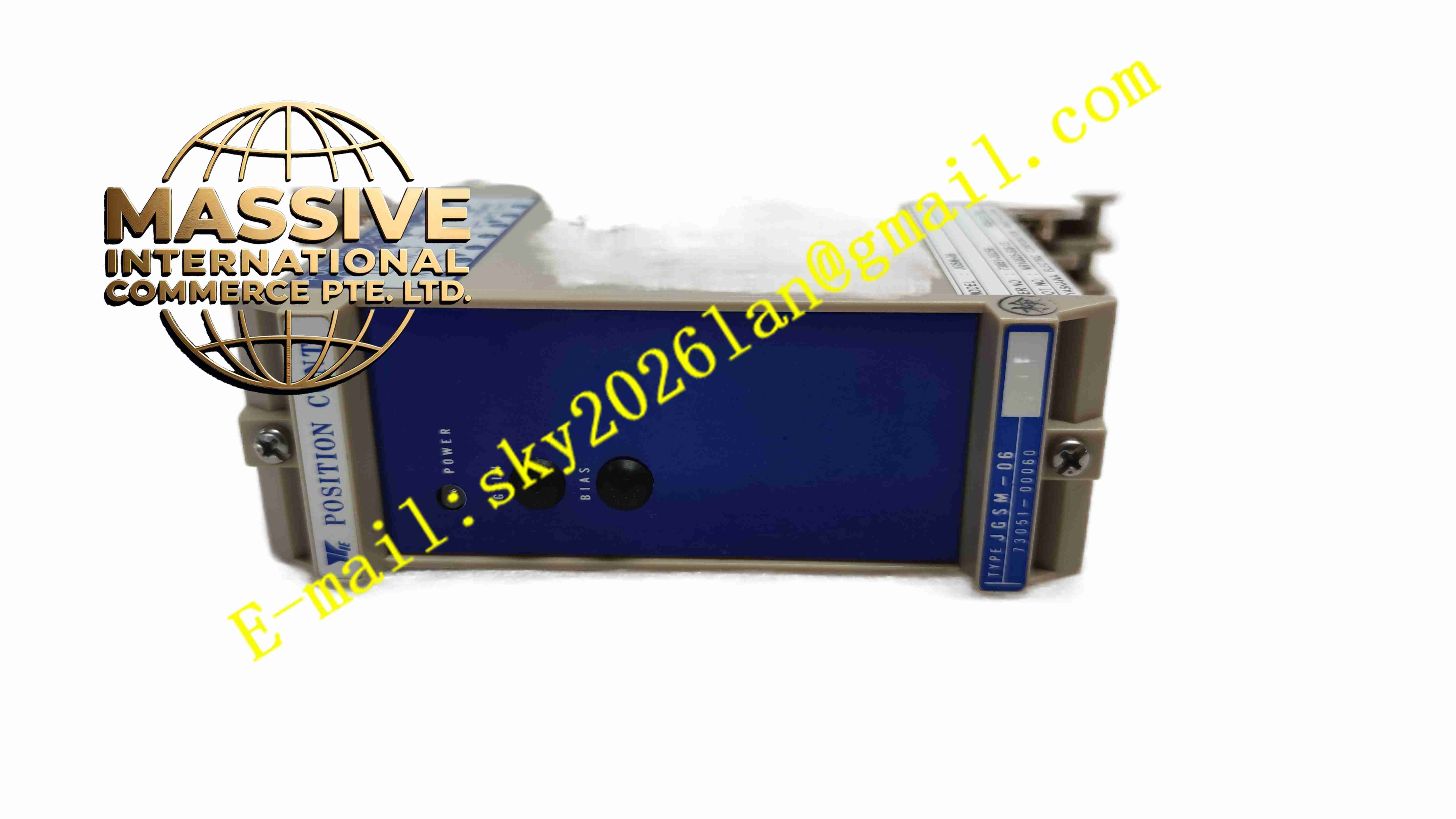
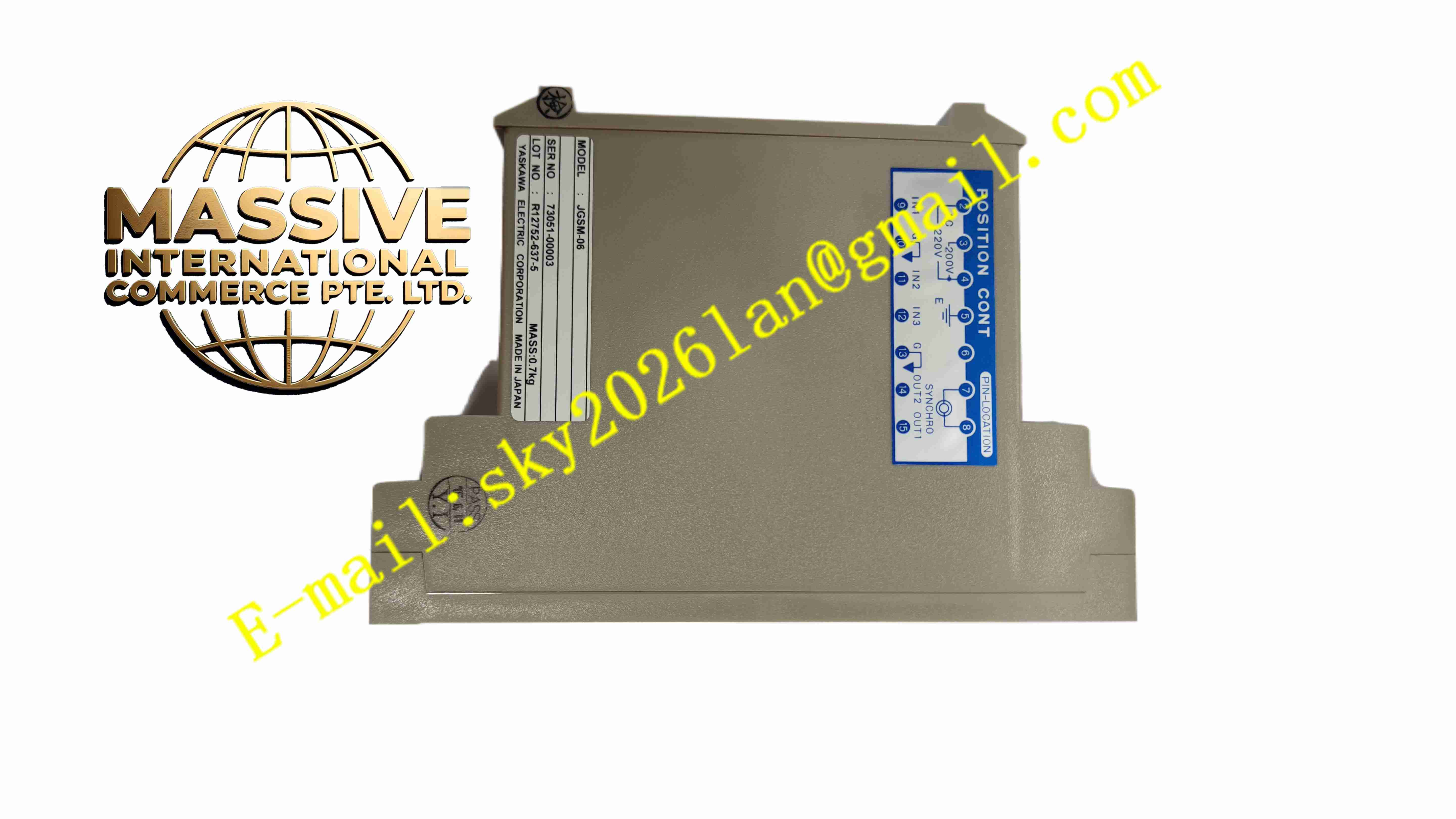
Yaskawa JGSM-06
Technical Specifications
- Compatible inverters: Yaskawa G7, A1000, GA700
- Protocol: DeviceNet / Profibus-DP
- Bus rate: DeviceNet up to 500 kbps, Profibus up to 12 Mbps
- Node address: DIP switch setting
- Supply: Inverter internal DC5V
- Isolation: Optically isolated between bus and main circuit
- Temperature: -10 °C to +50 °C
- Storage: -20 °C to +65 °C
- Humidity: 95 % non-condensing
- Protection: IP00 (inside inverter)
- Installation: Inverter control board expansion slot
Functional Features
- Plug into inverter expansion slot for fieldbus communication
- Supports DeviceNet or Profibus-DP
- Reads frequency reference and run command over bus
- Uploads inverter running status and fault codes
- DIP switch node address
- Bus optically isolated from main circuit
- On-board LEDs indicate communication status
- Simple installation with no external space
- Industrial-grade components tolerating high internal inverter temperature
- Matched to Yaskawa inverter firmware
Application Scenarios
- Yaskawa inverter DeviceNet bus integration
- Factory automation inverter Profibus-DP control
- Packaging and textile machine inverter bus speed control
- Elevator and crane inverter remote control
- Fan and pump inverter centralized monitoring
Materials and Construction
- PCB: FR4 board
- Communication: Bus protocol ASIC and isolated transceiver
- Passive components: Resistors and capacitors
- Connector: Inverter control board dedicated gold-plated connector
- Terminals: Dedicated bus terminals
- Housing: None (board inside inverter)
Structural Features
- Small PCB board inserted into inverter control board expansion slot
- Bus wiring terminals at inverter external terminal area
- On-board LEDs indicating communication
- DIP switches for node address
- Board communicates via connector to control board
- No independent housing, installed inside inverter
Working Principle After inserting into the inverter expansion slot, the board is powered by internal DC5V. The upper PLC sends frequency reference and run command over the fieldbus; the board converts bus data to internal inverter control signals to modify frequency and start/stop. Running status, current, voltage, and fault codes are uploaded via the board. DIP switches set node address. LEDs indicate data transmit/receive.
Installation Requirements
- With inverter input power off, open cover and insert board into expansion slot
- Connect bus cable to inverter external bus terminals
- Set node address by DIP switches
- Terminate both ends of bus with 120 Ω resistor
- After re-power, select communication protocol in parameter menu
- Cabinet temperature -10 °C to +50 °C
- Verify bus address uniqueness after power-up
Precautions
- Install or remove the board only with input power disconnected
- Wait for internal capacitor discharge before service
- Use shielded twisted pair for bus cable
- Node addresses must not duplicate other devices on the bus
- Check protocol selection and termination resistor on communication faults
- Store spares in anti-static packaging