Description
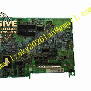
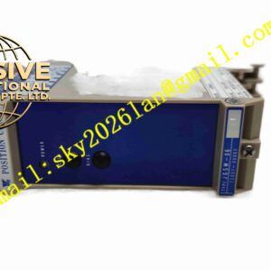
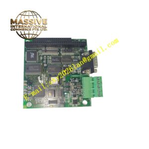
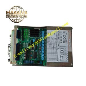
Yaskawa JRMSI-120XBP01200
Technical Specifications Multi-slot servo backplane; DC bus power distribution; High-speed control signal bus; Gold-plated module connectors; Rack mounting; Power distribution capacity matched to JRMSI series servo modules.
Functional Features Distribute DC bus power to each servo slot; Transmit high-speed control bus signal between modules; Mechanical positioning and locking for plug-in servo modules; Bus signal impedance matching; Built-in bus surge protection; Module power supply interlock function.
Application Scenarios Yaskawa JRMSI series multi-axis servo rack; Large automation production line multi-axis motion control; Machine tool integrated servo control cabinet.
Performance Parameters Operating temperature 0℃ to +55℃; Storage temperature -40℃ to +85℃; Relative humidity 10% to 90% no condensation; Withstand large DC bus current.
Material Composition Thick copper multi-layer power PCB; Gold-plated module edge connectors; High-current copper traces; Surge suppression components; Metal fixing brackets; Screw power terminals.
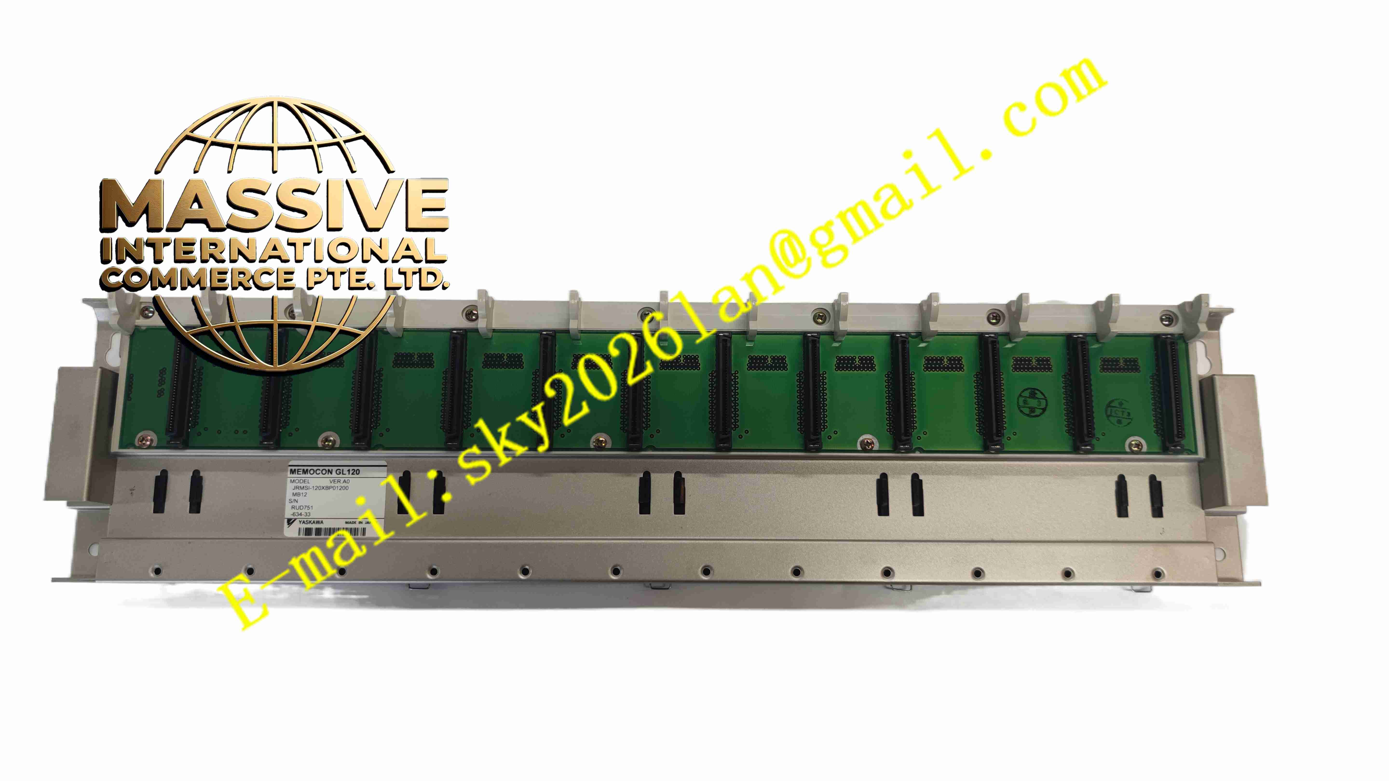
Structural Characteristics Long strip rack back plate; Multiple vertical module slots arranged side by side; High-current power traces and signal traces separated on PCB; Metal fixed bracket to install inside control cabinet.
Working Principle Main DC power supply connects to backplane power terminals. Backplane internal copper traces distribute DC bus power to each servo module slot. High-speed control bus signal traces realize communication connection between CPU module and each servo amplifier. All modules plug onto backplane to share power and control bus.
Installation Requirements Install backplane on cabinet mounting frame and tighten fixing screws. Connect main DC power cable to backplane power terminals. Insert servo and CPU modules one by one after power cut. Check all module locking status. Complete cabinet protective earthing before power-on.
Usage Notes Never plug or unplug modules when DC bus power is present. Check terminal tightness regularly for high current circuit. Do not scratch gold-plated connectors. Keep PCB surface clean without metal dust.