Description
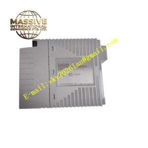
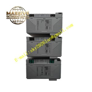
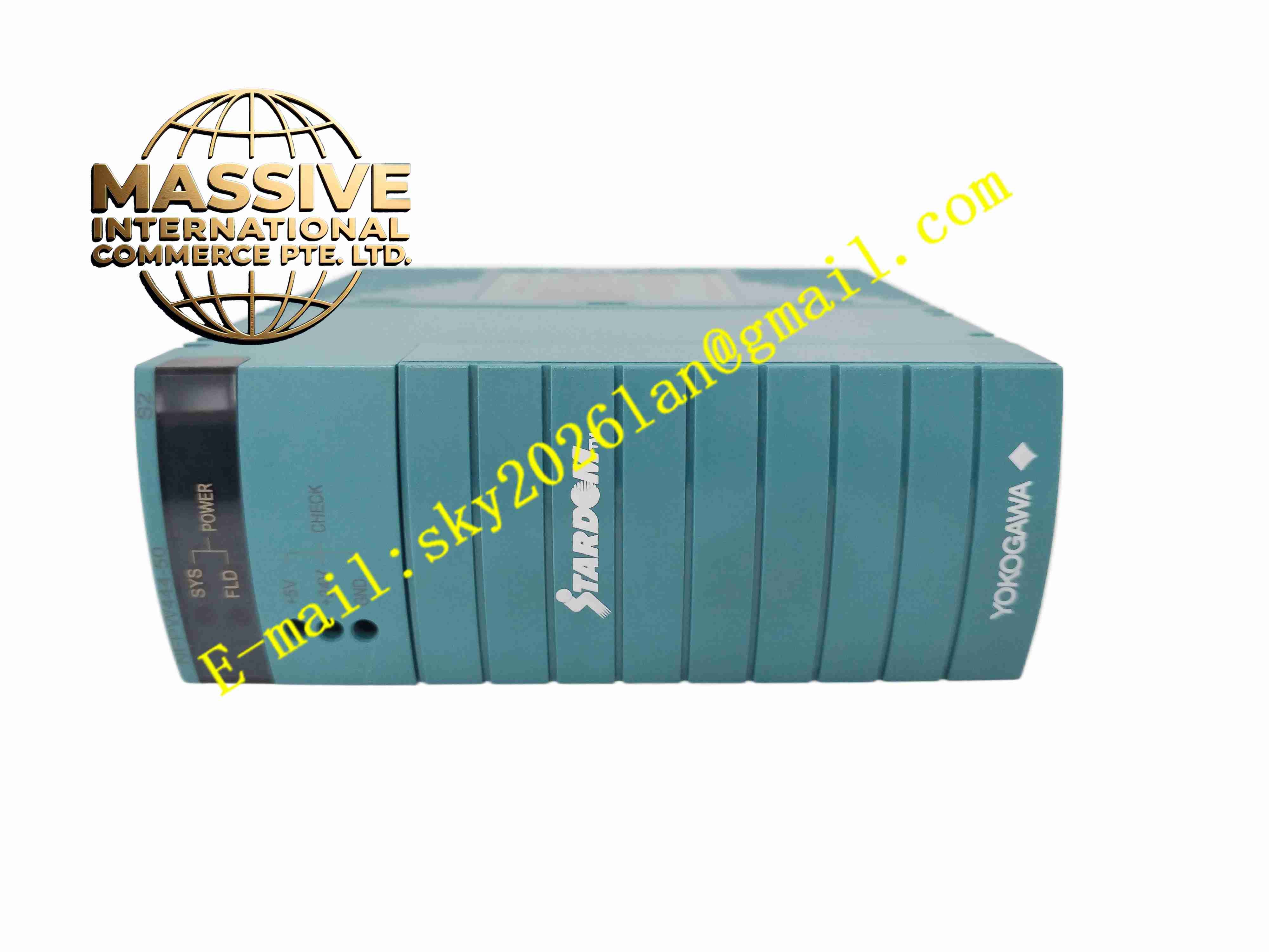
Yokogawa NFPW444
Technical Specifications: Input voltage range: 21.6 V DC to 31.2 V DC Main output voltage: +5.1 V DC Continuous rated output power: 40 W Peak output power: 60 W Continuous rated output current: 7.8 A Peak output current: 11.8 A Overvoltage protection threshold: Max 7 V DC Overcurrent protection: Activates at minimum 105% rated current Power on startup time: Maximum 300 ms Operating temperature range: 0℃ ~ +60℃ Storage temperature range: -40℃ ~ +85℃ Relative humidity: 5% to 95%, non-condensing Insulation resistance: 50 MΩ at 500 V DC Form factor: Two-slot width rack plug-in module Protection grade: IP20 when installed inside control cabinet
Functional Features: Convert wide-range 24V DC field power into stable regulated low voltage for system backplane. Supply auxiliary 24V analog field power for field instrument loops. Integrated overvoltage, overcurrent and over-temperature protection to cut off output under fault condition. Resist short duration power dip, maintain stable operation during momentary power failure. LED indicators on front panel to show power supply status and fault alarm. Continuous hardware self-diagnosis for internal circuit abnormality. Conformal coating option available for high humidity, corrosive industrial environment. Support hot swap compatible chassis for non-stop system maintenance.
Application Scenarios: Distributed fiber temperature monitoring system DTSX200, oil and gas pipeline temperature detection, refinery process control cabinet, chemical plant FCN controller system, power plant auxiliary control, offshore platform automation control, tunnel fire temperature monitoring system.
Performance Parameters: Hold stable output voltage under input voltage fluctuation within rated range. Fast protection response upon overcurrent, short circuit and overvoltage fault. Resist momentary power interruption of minimum 10 ms at 80% load. Continuous operation: 24 hours uninterrupted long-term operation in industrial control cabinet. Low output ripple to avoid interference to high precision analog measurement modules.
Material Composition: Circuit substrate: Multi-layer FR4 glass fiber epoxy printed circuit board. Core components: DC-DC power conversion chip, power MOSFET, output rectifier, overvoltage detection IC. Front panel: Black flame retardant ABS plastic with printed silk screen and LED transparent windows. Backplane connector: Gold plated copper alloy contact pins with anti-oxidation treatment. Internal passive components: Industrial grade high temperature capacitors and resistors. PCB surface treatment: Conformal coating available for corrosive environment variants.
Structural Features: Standard two-slot rectangular plug-in board structure matching Yokogawa chassis. Front panel fitted with power status LED and fault indicator LED. Internal circuit layout separated into input filter area, DC-DC conversion area, output regulation and protection area. Built-in mechanical locking latch to fasten module firmly into chassis slot. Internal isolation barrier between input power circuit and low voltage control circuit. Heat conduction structure for power components to dissipate heat to front panel and chassis air flow.
Working Principle: 24V DC input power enters the module through backplane connector. Input filter circuit suppresses surge and high frequency noise from field power line. DC-DC conversion circuit converts wide range DC input into regulated +5.1V DC output for chassis backplane. Auxiliary power circuit provides 24V DC field power supply for field analog instruments. Voltage and current monitoring circuits continuously sample output parameters. When output exceeds preset threshold value, protection circuit shuts down power output immediately and triggers fault indicator. The module resumes normal operation automatically after fault condition disappears and power restores.
Installation Requirements: Cut off chassis power supply before inserting or removing the module. Insert NFPW444 into designated two-slot position inside Yokogawa rack and lock mechanical latch. Complete backplane bus connection via chassis internal backplane. Connect 24V DC field power cable to module power terminals following wiring specification. Ensure control cabinet protective earth ground connection is reliable. Leave sufficient air flow clearance around module for heat dissipation. Do not install module next to high heat generating power modules without spacing.
Usage Notes: Backup system configuration before module replacement. Check input DC voltage range before powering on the module. Regularly inspect LED indicator status and terminal connection tightness. Wear anti-static wristband during module handling and replacement. Do not expose module to environment beyond rated temperature and humidity range. Prevent conductive dust, metal debris and liquid from entering module circuit region. Do not use module without proper chassis grounding.