Description
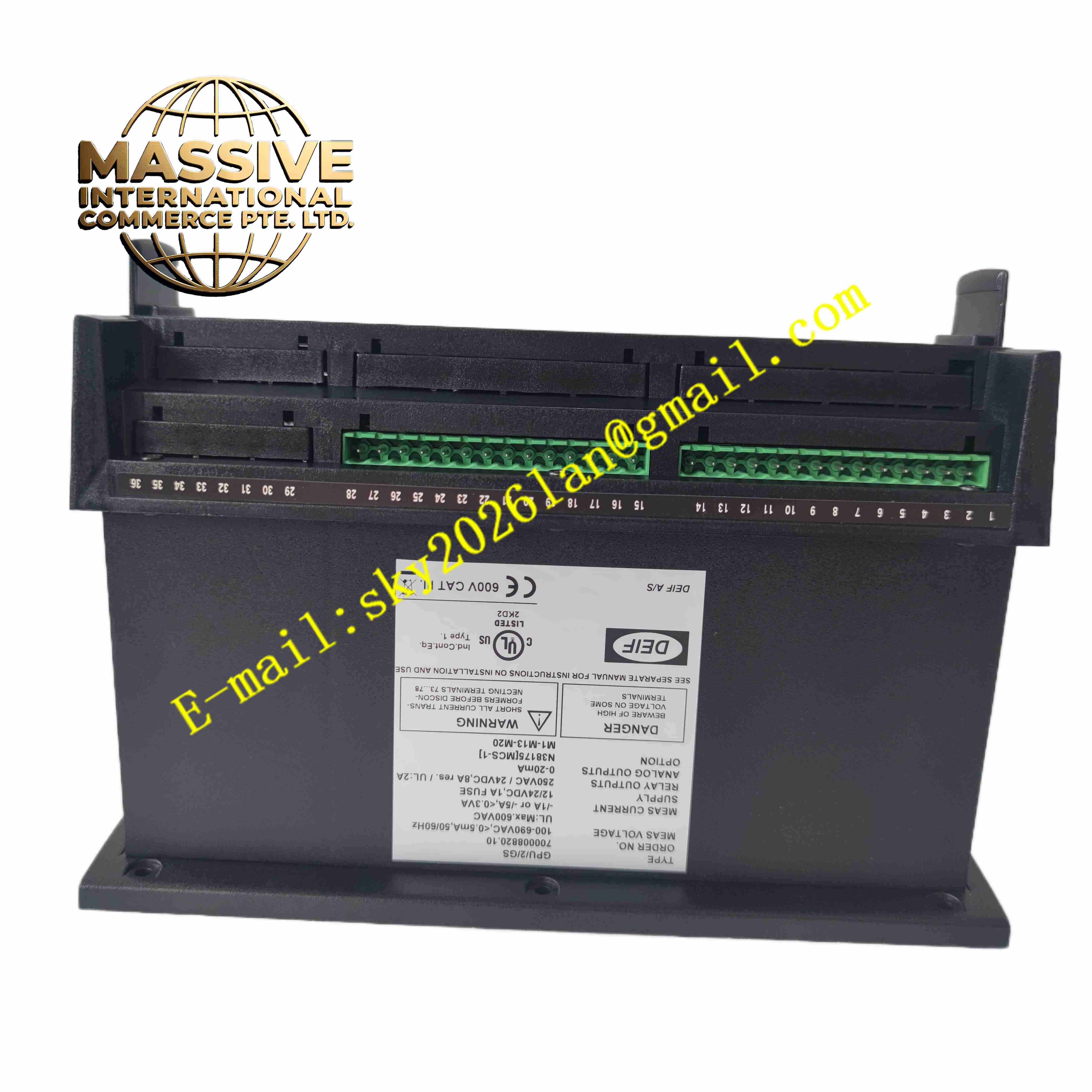
DEIF GPU2GS
Technical Specifications
- Product Type: Generator protection and synchronisation controller
- Power Supply: 24 V DC, 80-250 V AC universal power option
- Measurement Input: 3-phase voltage, 3-phase current
- Voltage Measurement Range: 0-690 V AC direct measurement
- Current Input: CT secondary 1 A or 5 A
- Measurement Accuracy: Class 0.5
- Digital Input Channels: 8 programmable 24 V DC discrete inputs
- Digital Output Channels: 8 relay outputs for trip, alarm and actuator control
- Communication Interfaces: Modbus RTU, optional Ethernet Modbus TCP
- Protection Functions: Overvoltage, undervoltage, overfrequency, underfrequency, reverse power, overcurrent, loss of excitation
- Protection Certification: IEC 60255 marine type approval
- Protection Rating: IP20 for front panel, IP20 rear terminal area
- Operating Temperature: -25 °C to +70 °C
- Mounting: Panel cutout mounting for control cabinet door
- Display: Backlit LCD graphic display with push-button operation
Functional Features
- Complete three-phase electrical parameter measurement for generator and busbar.
- Automatic synchronisation function with voltage, frequency and phase angle matching control.
- Built-in comprehensive generator electrical protection with configurable trip and alarm thresholds.
- Reverse power protection prevents generator motoring damage when mains power feeds back.
- Isolated digital inputs collect breaker status, emergency stop and limit signals.
- Relay outputs control generator breaker, fuel valve and local alarm indicators.
- Load sharing and power regulation for parallel running of multiple generators.
- Event log records alarm, trip and synchronisation events with real-time timestamp.
- Password protected parameter configuration prevents unauthorised setting modification.
- Modbus communication uploads real-time generator data and fault information to SCADA or PLC.
Application Scenarios
- Marine vessel main generator and emergency generator control
- On-site backup power generator plant synchronisation and protection
- Combined heat and power genset parallel operation system
- Remote island power station generator management
- Data centre standby generator protection and synchronisation
Material Composition
- Front housing: Flame-retardant ABS plastic
- Main PCB: FR4 printed circuit board with conformal coating
- Signal acquisition components: High precision voltage and current sampling circuits
- Processor: Industrial grade 32-bit microcontroller
- Relay components: Electromagnetic safety relays for trip outputs
- Terminal blocks: Tin-plated copper alloy screw terminals
- Display module: LCD screen with LED backlight
Structural Characteristics
- Panel mount rectangular unit with front operating panel.
- Front panel integrates LCD display and membrane push buttons.
- Rear terminal blocks for voltage, current CT, digital I/O and power supply wiring.
- Internal circuit separates high voltage measurement circuit and low voltage logic circuit.
- Internal EMC shielding suppresses electrical noise from generator engine and ignition systems.
- Compact panel cutout design for standard control cabinet door installation.
Working Principle GPU2GS samples voltage and current signals from generator and busbar via voltage transformers and current transformers. Internal processor calculates frequency, phase angle, active power and reactive power continuously. When synchronisation sequence starts, the controller adjusts governor and AVR to match voltage, frequency and phase between generator and busbar. Once synchronisation conditions are satisfied, the controller sends closing command to generator circuit breaker. If electrical parameters cross protection thresholds, the controller triggers trip relay to open breaker and shut down generator fuel supply, and stores fault event records.
Installation Requirements
- Install controller on control cabinet door with specified panel cutout dimensions.
- Use shielded twisted pair wiring for CT and VT measurement circuits.
- Separate high voltage measurement wiring from low voltage digital signal wiring.
- Complete protective earth connection to cabinet ground bar.
- Set CT ratio, voltage range and protection threshold parameters before commissioning.
- Perform synchronisation simulation and protection trip test with test equipment.
- Verify breaker feedback wiring continuity and polarity.
Usage Notes
- Do not exceed rated voltage and current input limits for measurement terminals.
- Disconnect CT secondary circuit before opening current transformer wiring.
- Keep cabinet dry and free of oil mist and conductive dust.
- Perform periodic protection function test according to genset maintenance schedule.
- Backup parameter settings before firmware upgrade or configuration modification.
- Use anti-static wristband when handling the controller unit.
- Replace controller immediately when permanent measurement or logic fault occurs.