Description
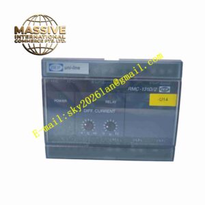
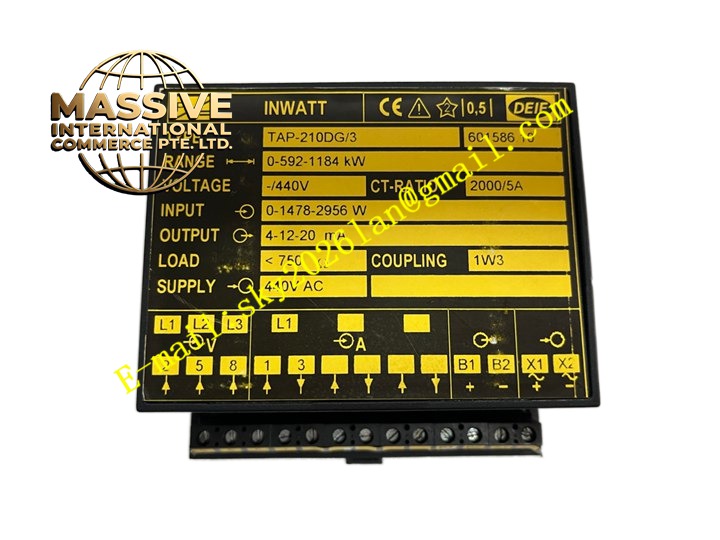
DEIF TAP-210DG3
Technical Specifications Three-phase current and voltage analog input; Protection functions: overcurrent, overload, earth fault, negative sequence overcurrent; Power supply DC24V or AC85-264V; Operating temperature -20°C to +70°C; Relay trip output contacts; LCD local display; Event record with time stamp; LED fault status indicators.
Functional Features Integrated multiple transformer protection functions within single unit; Adjustable protection setpoints via front panel keys or communication; Hard relay trip output independent from internal processor; Fault event log stores time stamped fault records; Three-phase electrical parameter measurement including current, voltage and power; LED indicators show fault type directly; Modbus communication for remote monitoring and configuration; Built-in protection test function.
Application Scenarios Distribution transformer protection in industrial plant; Solar power station step-up transformer; Commercial building power transformer; Wind farm auxiliary transformer; Water treatment plant power transformer; Mining site distribution transformer.
Performance Parameters Protection operation response speed meets power system protection standard; Electrical measurement precision is high; Event data remains stored after power loss; Setpoint adjustment resolution fine; Immunity to power grid harmonic interference.
Material Composition Metal reinforced enclosure; Multi-layer glass fiber PCB; Current and voltage sampling circuit; High precision analog converter; Microprocessor; Electromagnetic trip relays; Front panel LCD screen and operation keys; LED fault indicators; Conformal coating on circuit board.
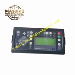
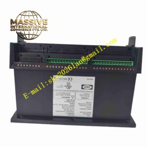
Structural Features Panel embedded mounting design; Front panel LCD display and operation push buttons; Multi-color LED fault indicators; Rear large screw terminal block for CT, PT, trip circuit and power wiring; Sealed front panel to resist dust and moisture.
Working Principle CT and PT send three-phase current and voltage signals to relay sampling circuit. The internal processor continuously calculates electrical parameters of transformer. When measured value exceeds preset protection threshold, relay contact energizes and outputs hard trip signal to open transformer circuit breaker. Fault type and time stamp are saved to non-volatile memory. Relay sends real-time measurement data and fault information to upper monitoring system via Modbus bus.
Installation Requirements Install relay through panel cutout inside control cabinet; CT secondary wiring must not operate under open circuit state; PT secondary circuit install short-circuit protection; Use shielded cable for signal wiring; Cabinet protective earth connection required.
Precautions for Use Modify protection setpoint only when transformer offline; Verify CT and PT wiring phase sequence before commissioning; Periodically perform protection trip test; Do not disconnect trip wiring while transformer is energized; Clean rear terminal block regularly in dusty environment.