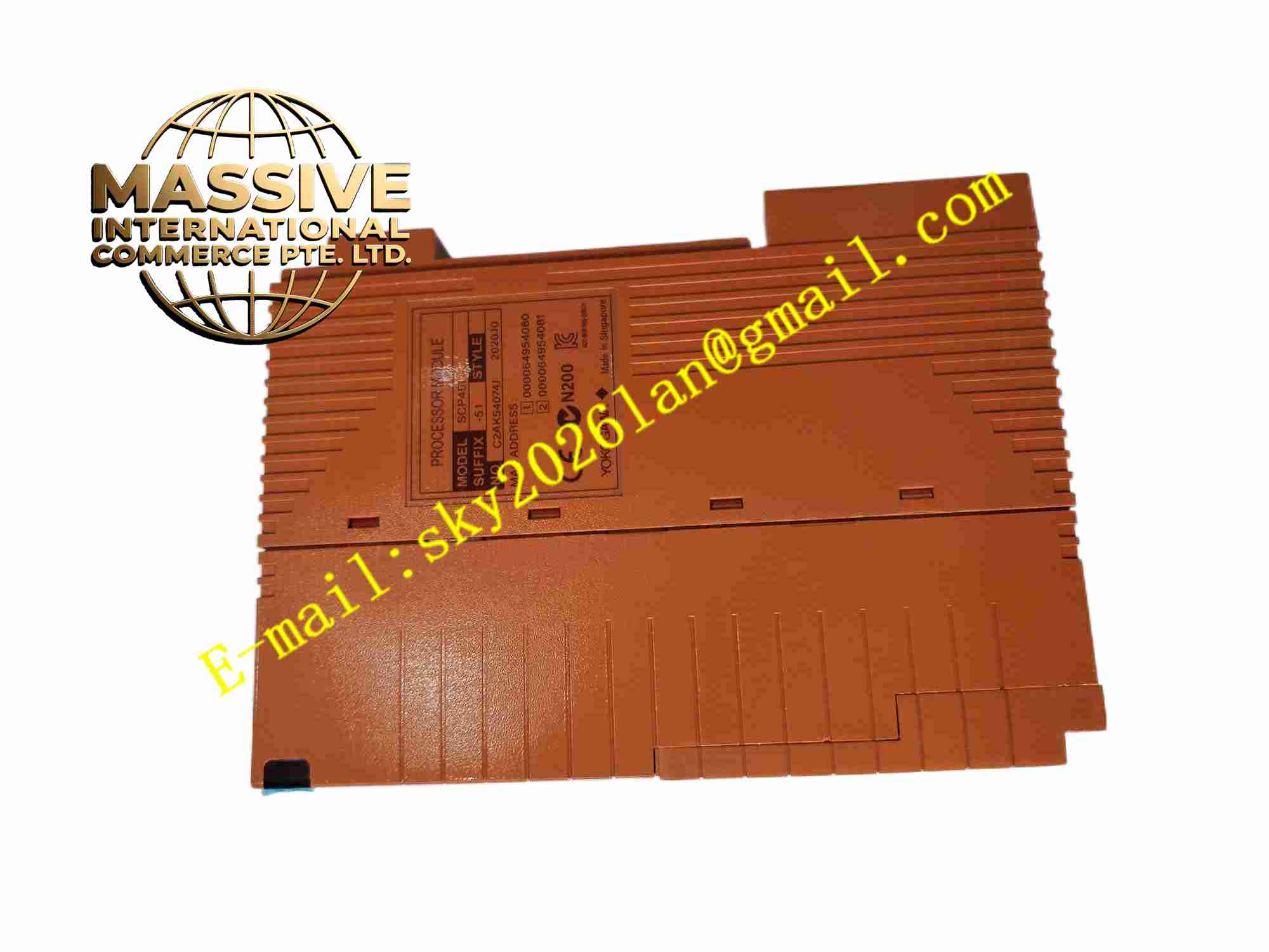
Description
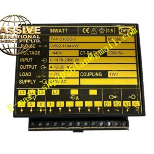
DEIF SCM-2 1044220110E
Technical Specifications: Power supply: 12 VDC or 24 VDC nominal Engine inputs: speed, oil pressure, coolant temperature, fuel level Generator measurements: voltage, current, frequency, power Display: LCD with backlight Operating temperature: -40 ℃ to 70 ℃ Protection class: IP54 front panel Communication: Modbus RTU
Functional Features: Automatic mains failure start and stop sequence. Engine and generator protection alarms. Over-speed, low oil pressure and high temperature shutdown. True RMS measurement of generator electrical parameters. Event log stores last 50 alarm events. LED indicators for running, alarm and trip status. Configurable relay outputs. Battery voltage monitoring.
Application Scenarios: Diesel generator set control panel, marine emergency generator controller, offshore platform genset protection, hospital backup generator control, data center genset management.
Performance Parameters: Voltage measurement accuracy: ±0.5% Frequency measurement accuracy: ±0.1 Hz Analog input resolution: 10 bit Relay output contact rating: 5 A, 250 VAC
Material Composition: Front panel: polycarbonate membrane keypad. Housing: UL94-V0 ABS plastic. PCB: FR-4 glass fiber epoxy. Terminal blocks: nickel-plated brass. LCD display: transmissive STN with backlight.
Structural Features: Panel-mount rectangular housing. Front membrane keypad and LCD display. Rear screw terminals for field wiring. Panel gasket for sealed front mounting. Integrated DIN rail mounting option.
Working Principle: Engine sensors send analog and digital signals to module input terminals. Generator voltage and current signals connect to measurement inputs. Module processes measured values and compares against user-set protection thresholds. When alarm threshold is exceeded, module activates corresponding relay output. Automatic start sequence activates when mains failure detected. Event log records alarm time and type.
Installation Requirements: Panel mount through cutout with provided gasket. Connect engine sensors and generator CT/PT secondaries. Route signal cables separately from high-voltage generator power cables. Connect battery supply with correct polarity. Ground panel mounting securely.
Precautions for Use: Disconnect battery supply before wiring. Verify CT and PT polarity before enabling protection functions. Do not exceed voltage measurement input range. Protect LCD from direct sunlight exposure. Calibrate engine sensor inputs during commissioning. Keep module away from excessive heat sources.