Description
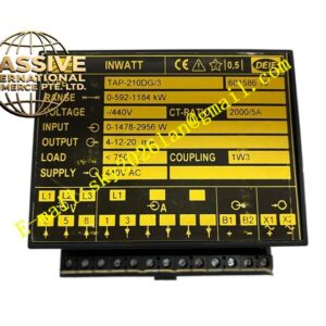
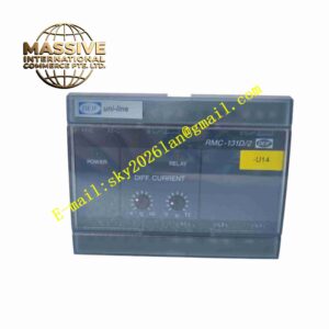
DEIF PPM3-6DG-6H3-1F1
Technical Specifications Model: PPM3-6DG-6H3-1F1 Measurement Type: Three-phase voltage and three-phase current Voltage Measurement Range: 0 ~ 120VAC Current Measurement: Accessible via external current transformers Frequency Measurement Range: 40Hz ~ 70Hz Power Supply: 24VDC or 85~250VAC wide range power supply Communication Interface: Modbus RS485 Digital Inputs: Multi-channel binary signal input Relay Outputs: Multiple programmable relay contact outputs Operating Temperature: -20℃ ~ +70℃ Storage Temperature: -40℃ ~ +85℃ Relative Humidity: 5% ~ 95% non-condensing Mounting: Panel cutout mounting Front Panel Protection: IP52
Functional Features Real-time measurement and display of three-phase voltage, current, active power, reactive power, power factor and frequency. Built-in multiple electrical protection functions including overvoltage, undervoltage, overcurrent, overfrequency, underfrequency, reverse power protection. Programmable relay outputs for alarm signal and circuit breaker trip command. Modbus RS485 communication transmits measurement data and fault information to PLC or SCADA system. Digital input channels collect external status signals such as circuit breaker position and emergency stop. Front panel LCD display shows real-time electrical parameters and fault event records. Event log function stores fault timestamp records for post-fault analysis. Parameter setting and function configuration via front panel keys or software tool.
Application Scenarios Diesel generator control panel, marine power distribution system, industrial standby generator set, grid-connected generator protection, microgrid power monitoring, factory main power distribution cabinet.
Performance Parameters Voltage and current measurement maintains high precision in full operating temperature range. Protection functions trigger within fixed response time when electrical threshold is exceeded. Event log records fault data with accurate time stamp and data will not lose after power off. Modbus communication maintains stable data transmission under industrial electromagnetic environment. Relay contact has long mechanical service life for repeated alarm and trip operation. All protection threshold parameters keep stable without drift after long-time continuous running.
Material Composition Front housing: Flame-retardant black ABS engineering plastic. Display window: Transparent scratch-resistant plastic window. Internal PCB: FR4 multi-layer industrial printed circuit board with conformal coating. Core Electronic Components: Microcontroller chip, voltage sampling circuit, current sampling circuit, A/D converter, LCD driving chip, relay, communication transceiver chip, memory chip. Sealing component: Rubber sealing ring. Fasteners: Plastic fixing buckles and metal screws. Terminal block: High-current flame-retardant plastic terminal block.
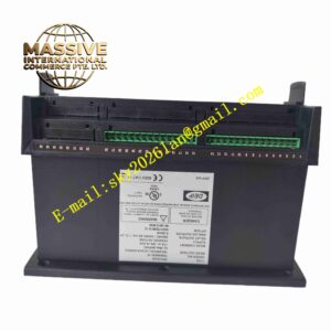
Structural Features Rectangular panel mounting structure for cabinet cutout installation. Front panel equipped with LCD screen, function keys and LED status indicators. Rubber sealing ring between front panel and cabinet plate to realize front IP52 protection. Rear housing accommodates main circuit board and screw terminal blocks for wiring. Internal circuit layout separates high voltage sampling circuit, low voltage control circuit and communication circuit. Terminal blocks are arranged on rear side for voltage, current, digital signal and communication wiring.
Working Principle After power supply is connected, the relay samples three-phase voltage and current signals from voltage transformer and current transformer. Analog signals pass through signal conditioning circuit and enter A/D converter, converting analog electrical quantity into digital data for microcontroller processing. The microcontroller calculates voltage, current, frequency and power parameters. Measured values are compared with preset protection thresholds continuously. When measured value exceeds protection threshold, corresponding relay contact acts to send alarm or trip signal. Measurement data and fault event information are stored in internal memory. Modbus module transmits real-time data and fault records to upper monitoring system through RS485 bus. LCD screen refreshes and displays electrical parameters and alarm messages.
Installation Requirements Cut rectangular opening on control cabinet panel according to dimension drawing. Insert relay from front of panel and fasten rear mounting brackets. Install rubber sealing ring to guarantee front panel protection rating. Connect voltage and current signal wiring to rear terminals, follow CT polarity requirement strictly. Connect digital input, relay output and RS485 communication wiring. Use shielded twisted pair cable for RS485 communication wiring. Check wiring polarity and short circuit before power on. Set rated parameters and protection thresholds via front keys or configuration software. Complete function test of each protection item after parameter configuration.
Usage Precautions High voltage signal is connected to voltage terminals, wiring operation must be performed under power-off condition. CT secondary side must not be open circuit during operation, otherwise dangerous high voltage generates. Do not touch rear terminal block when device is powered on. Check wiring terminal tightness periodically, especially in high vibration environment. Avoid conductive dust and condensation on rear terminal area. Parameter modification should be recorded for equipment maintenance. Do not open rear plastic housing without professional authorization.