Description
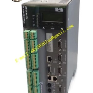
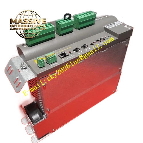
ELAU PS‑5.VPMO2D20AA00
Technical Specifications: Three‑phase AC input 380‑480 VAC, input frequency 50 / 60 Hz, DC‑link output 565‑680 VDC, rated output power 20 kW, maximum DC bus current 35 A, built‑in braking chopper interface, internal EMC filter, protection class IP20.
Functional Features: Centralized DC‑bus power supply for multi‑axis groups, regenerative energy absorption via external brake resistor, hardware over‑voltage, under‑voltage, over‑current and over‑temperature protection, status LED indicator lights for power and fault conditions, DC bus parallel expansion capability, diagnostic signal relay output for system fault alarm.
Application Scenarios: Multi‑axis packaging machines, printing converting equipment, automated production lines, textile machinery, high‑speed material processing machinery, PacDrive3‑based automation platforms.
Performance Parameters: Power‑supply efficiency 96 %, operating ambient temperature 0 °C to +55 °C, derating required above 45 °C, short‑circuit protection response time less than 10 ms, compatible with VDM series servo drives.
Material Composition: Metal sheet‑steel enclosure, copper‑bus power circuit, IGBT power semiconductor components, high‑voltage film DC‑link capacitors, reinforced plastic terminal block insulators.
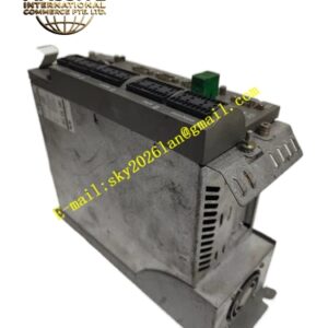
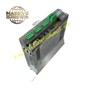
Structural Characteristics: Standard DIN‑rail cabinet mounting structure, front‑side power wiring terminals, status LED viewing window on front panel, internal power‑section and control‑section physical separation, upper‑to‑lower forced‑air cooling airflow path.
Working Principle: Three‑phase alternating current passes through EMC filter and uncontrolled rectifier bridge to generate high‑voltage DC‑link voltage. Internal monitoring circuits continuously sample bus voltage, output current and component temperature. Excess regenerative energy from motor deceleration is directed to external brake resistor via integrated chopper circuit. Fault signals are transmitted through relay contact output to upper‑level control system.
Installation Requirements: Install inside IP20 industrial control cabinet; maintain specified top‑and‑bottom ventilation clearance for cooling airflow; use designated high‑voltage power cables for AC input and DC bus connection; connect protective earth terminal to cabinet protective ground bar; keep minimum 100 mm separation distance from signal‑level control cables.
Usage Notes: Confirm correct three‑phase mains phase sequence before power‑on; connect external brake resistor matching power rating when frequent high‑energy deceleration occurs; do not open enclosure cover while power remains connected; avoid operation in environments with conductive dust or corrosive gas; implement pre‑charge sequence for parallel‑connected multiple power‑supply units.