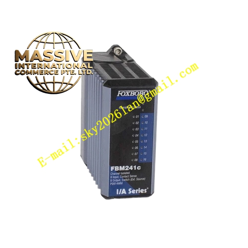
Description
Foxboro FBM241C
Technical Specifications
- Product Type: 8-Channel Analog Output Module.
- Output Signal: 4-20 mA DC (standard).
- Channel Count: 8 isolated output channels.
- Resolution: 16-bit Digital-to-Analog (D/A) conversion.
- Communication: Redundant 2 Mbps Module Fieldbus.
Functional Features
- High-Accuracy Output: Precision D/A conversion ensures the field device receives the exact commanded signal, minimizing process variability.
- Channel Isolation: Galvanic isolation between channels prevents ground loops and cross-channel interference.
- Comprehensive Diagnostics: Provides open-loop detection, output saturation alarms, and field wire break monitoring.
- Hot-Swap Capability: Allows for module replacement without shutting down the system or disrupting the control loops.
Application Scenarios
Essential in any continuous process control application for manipulating final control elements to maintain process variables (pressure, temperature, flow, level) at their desired setpoints.
Performance Parameters
- Accuracy: ±0.1% of span.
- Loop Resistance: Capable of driving standard 250-600 ohm loops.
- Response Time: Fast update rates (typically <100ms) for dynamic control loops.
- Output Ripple: Extremely low ripple for smooth valve positioning.
Material Composition
Industrial-grade electronic components on multi-layer PCBs with conformal coating for environmental protection. Housed in a rugged aluminum enclosure for EMI protection and efficient heat dissipation.
Structural Characteristics
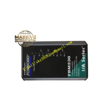
Standard FBM form factor that plugs directly into the I/A Series backplane. Features a front-panel high-density connector for field wiring and individual LED indicators for channel status and module health.
Working Principle
The module receives digital output values from the controller via the backplane. A high-resolution digital-to-analog converter (DAC) transforms these values into a precise current signal. An internal feedback loop regulates this current to ensure it matches the commanded value, regardless of loop resistance or temperature variations.
Installation Requirements
Install in a designated FBM slot on the backplane. Use shielded twisted-pair wiring for output signals. Ground the shield at the cabinet end only to prevent ground loops.
Usage Precautions
- Verify the loop resistance is within the module’s specifications to avoid saturation.
- Do not short-circuit output channels during operation.
- Perform periodic calibration checks using a precision multimeter to maintain accuracy.
- Ensure proper wiring polarity to prevent damage to field devices.