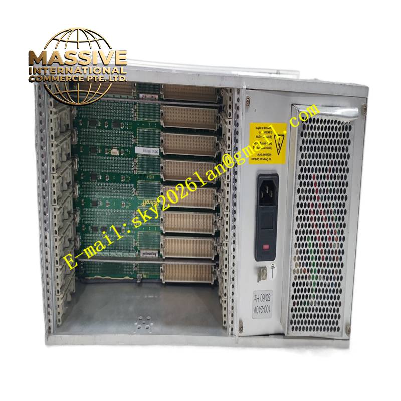
Description
Technical Specifications Rack plug-in form factor; multi-channel signal processing circuitry; backplane bus communication interface; industrial wide temperature operating range; on-board status LED indicators; anti-surge protection circuits for signal terminals.
Functional Features Receives analog and discrete feedback signals from field sensors and transducers. Filters and conditions raw field signals before sending data to the main processor. Transmits control commands from the main controller to external field devices. Runs continuous on-board hardware self-diagnosis and reports fault states to the host system. Supports hot swap maintenance in compatible GE control racks.
Application Scenarios Gas turbine control systems, generator auxiliary control cabinets, large motor protection systems and heavy industrial power generation automation platforms.
Performance Parameters High signal sampling precision; low signal noise and distortion; stable communication throughput on the backplane bus; robust resistance to industrial vibration and electromagnetic interference.
Material Composition Main substrate is FR-4 high-reliability multilayer flame-retardant PCB; signal processing chips are industrial wide-temperature semiconductor components; backplane connector contacts are gold-plated; terminal hardware is nickel-plated copper alloy; surface components are protected by conformal coating.
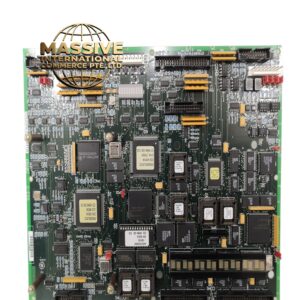
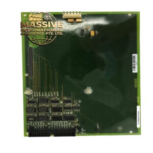
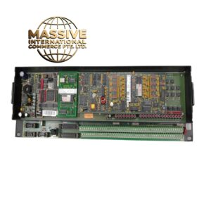
Structural Characteristics Rectangular plug-in card designed for standard GE equipment racks; metal front panel with status indicator lights and locking hardware; rear gold finger connector for mating with rack backplane; fixed mounting lugs and screws on the front edge.
Working Principle Field sensor signals enter the board through external wiring terminals. Signal conditioning circuits remove high-frequency noise and adjust signal levels to match the analog-to-digital converter input range. The onboard logic circuit exchanges data and control instructions with the rack main processor via the backplane bus. Built-in diagnostic circuits continuously monitor power supply and channel integrity during operation.
Installation Requirements Cut off rack main power before installation unless the rack supports certified hot replacement. Align the gold fingers with the backplane slot and insert the card smoothly. Tighten the front panel locking screws to maintain stable electrical contact. Complete channel wiring and function verification after power restoration.
Precautions for Use Follow static control procedures when handling the board. Do not touch exposed gold finger contacts. Separate signal wiring from high-current power cables. Replace the assembly when persistent hardware faults appear and do not attempt to repair internal circuit traces.