Description
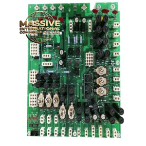
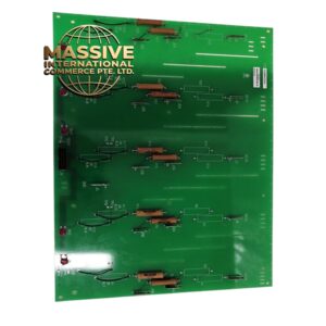
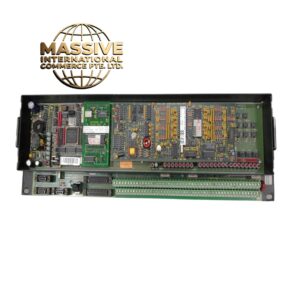
GE A16B-2200-0490
Technical Specifications Multi-slot connector layout for daughter boards; system bus trace routing; on-board signal buffer circuits; matched to POWERMATE A CNC hardware; rack plug-in PCB form; 24V DC system power distribution traces.
Functional Features Distributes regulated DC power from the power supply module to each daughter board slot. Transmits address, data and control signals over parallel system bus between CPU, memory and I/O boards. Integrates signal buffering circuits to improve bus driving capability. Provides physical mounting and positioning interface for all plug-in sub-boards of the POWERMATE A controller.
Application Scenarios Compact POWERMATE A CNC control cabinets for small CNC lathes, drill tap machines and simple automated machine controllers.
Performance Parameters Controlled impedance for parallel bus signals; stable power distribution with low voltage drop; consistent contact resistance at slot connectors; tolerance to cabinet vibration.
Material Composition PCB substrate is thick FR-4 flame-retardant multilayer material; slot connector pins are gold-plated copper alloy; signal buffer chips are industrial grade semiconductors; solder mask is durable green protective coating.
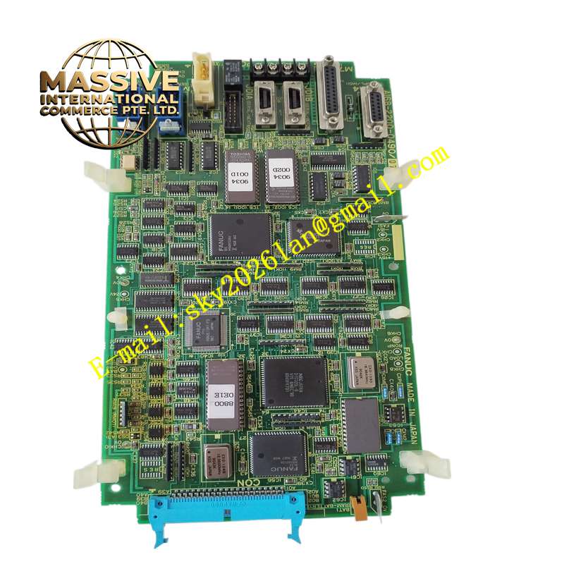
Structural Characteristics Large rectangular plug-in PCB; multiple edge card connectors arranged along the board for daughter board insertion; mounting holes for fixing inside the CNC chassis; printed silk screen marking for signal and power nets.
Working Principle Power supply module feeds DC voltage to the power traces on this base board. The CPU board sends address and data signals onto the parallel bus routed on the PCB. Each daughter board receives power and bus signals through its edge connector. Buffer chips strengthen signal levels to maintain reliable communication across the bus.
Installation Requirements Mount the base board securely inside the POWERMATE A chassis with original fasteners. Insert CPU, memory and I/O daughter boards vertically into the corresponding connectors. Inspect connector pins for bending or contamination before assembling sub-boards.
Precautions for Use Observe anti-static procedures during handling. Do not bend the PCB or scratch gold-plated connector fingers. Keep conductive dust and metal shavings away from the board surface. Do not modify PCB traces or add jumper wires.