Description
GE A20B-8101-0420
Technical Specifications Video signal generation circuit; touch or key input scanning interface; local frame buffer memory; parallel bus connection to CNC main CPU; 24V DC logic power supply; panel connector for display and keypad cables.
Functional Features Receives display content data from the CNC main controller and stores image frames in local buffer. Generates standard video signals to drive the CNC operator LCD display. Scans keypad or touch screen signals and transmits operator input events back to the main CPU. Supports screen refresh, character rendering and graphic element drawing for CNC HMI pages.
Application Scenarios Fanuc CNC machine operator panels for machining centers, lathes and grinders with built-in display and program editing functions.
Performance Parameters Stable video frame refresh rate; low input signal latency for keypad operation; stable frame buffer read-write operation; noise immunity for front panel wiring.
Material Composition PCB substrate is FR-4 flame-retardant multilayer board; graphic controller and buffer memory chips are industrial semiconductors; panel signal connectors are gold-plated; surface components are protected by conformal coating.
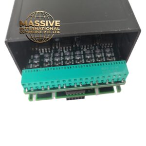
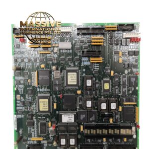
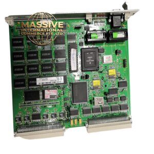
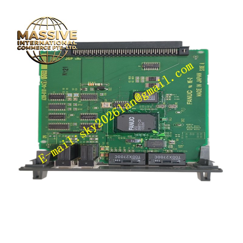
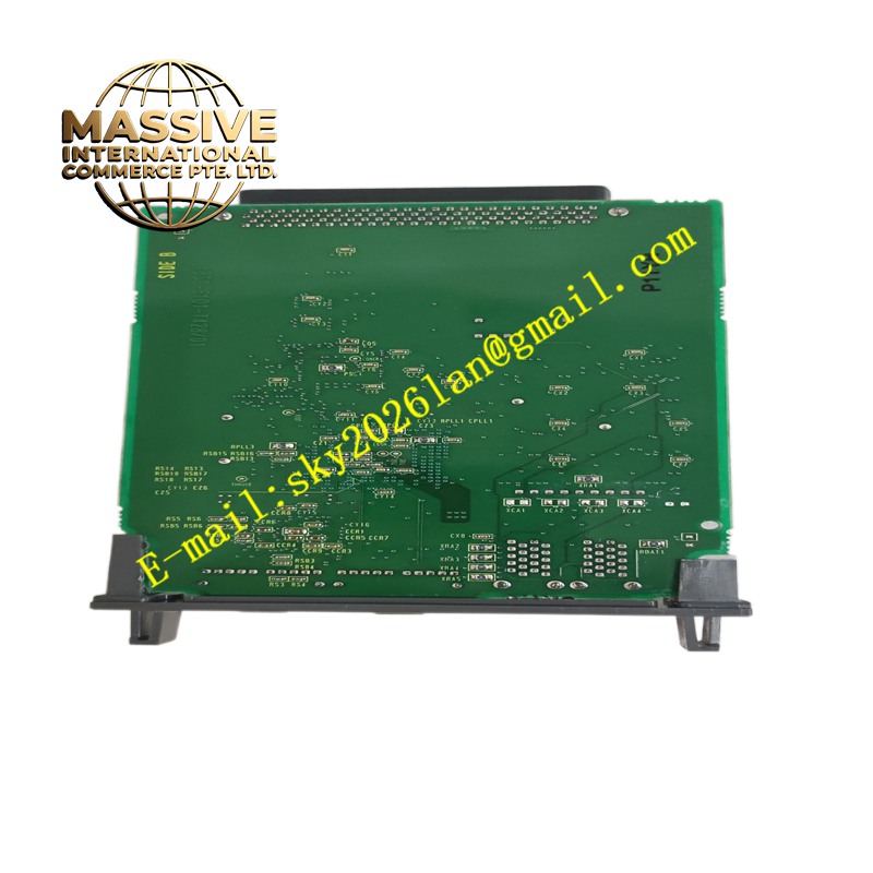
Structural Characteristics Plug-in PCB board; rear edge connector connecting with CNC main board bus; front side terminal connectors for LCD screen cable and operator keypad cable; status LEDs for video and input link.
Working Principle The CNC main CPU sends HMI page data including numbers, text and graphic coordinates to this graphic board. The onboard graphic controller composes the image into frame buffer memory and outputs video timing and pixel signals to the LCD display. When the operator presses keys or touches the screen, the scanning circuit captures the input coordinate or key code and sends it back to the main CPU for processing.
Installation Requirements Power down the CNC control unit before board replacement. Route display and keypad cables to the front panel connectors following pin definitions. Secure the PCB mounting fasteners inside the control cabinet. Power on and verify display brightness, touch response and key input function.
Precautions for Use Avoid pulling the thin display cable with excessive force. Do not operate the board with short-circuited keypad wiring. Check cable pin integrity if the screen shows no image or flickering.