Description
GE DS200PCTMG1A
Technical Specifications
- Product Series: GE Speedtronic Mark V.
- Board Type: RST Analog I/O Board (TCQA).
- Signal Processing: Scales and conditions 4-20 mA input signals (e.g., compressor stall detection, fuel flow pressure).
- Connectors: Features multiple specific connectors including 2PL (power), 3PL (data bus), JE, JFR, JG, and JD.
Functional Features
- Signal Conditioning: Processes LVDT inputs, servo valve outputs, thermocouple inputs, vibration inputs, and generator/line signals.
- Data Bus Communication: Utilizes the 3PL connector to transmit conditioned signals to the COREBUS via STCA, TCQA, and TCQE boards.
- Generator Signal Routing: Uses the JE connector to send and receive generator and line signals to/from the TCQC board.
- Trip Signal Routing: The JD connector sends trip signals from the core to the TCTG board.
Application Scenarios
Exclusively applied in gas turbine control systems, power generation plants, and heavy industrial turbine monitoring environments.
Performance Parameters
- Signal Types Handled: 4-20 mA, LVDT/LVDR, thermocouples, +/- 10 V DC, and pulse signals.
- Hardware Configuration: Features hardware jumpers J1, J2, J5, J6, J7, and J8 for configuring output circuits, current ranges, RS232 testing, and oscillator startup.
Material Composition
Constructed from industrial-grade multi-layer printed circuit boards (PCBs) populated with high-reliability analog conditioning integrated circuits, resistors, and precision connectors.
Structural Characteristics
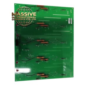
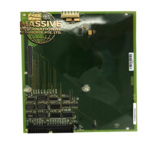
Standard Mark V board form factor designed to plug directly into the R1, R2, or R3 I/O cores, featuring multiple specialized ribbon and pin connectors on the board surface.
Working Principle
Raw analog signals from field sensors are routed through terminal boards into the DS200PCTMG1A. The board’s internal circuitry scales, filters, and conditions these signals before passing the digitized or conditioned data across the 3PL data bus to the main turbine controller for processing.
Installation Requirements
- Must be installed into the designated RST core slot in the Mark V rack.
- All associated ribbon cables (3PL, JE, JD) must be securely seated and locked.
- Hardware jumpers must be configured to match the specific turbine application prior to installation.
Usage Precautions
- Always wear an anti-static wrist strap when handling the board to prevent electrostatic discharge (ESD) damage.
- Never insert or remove the board while the turbine control system is energized.
- Verify all jumper settings against the system configuration manual before applying power.