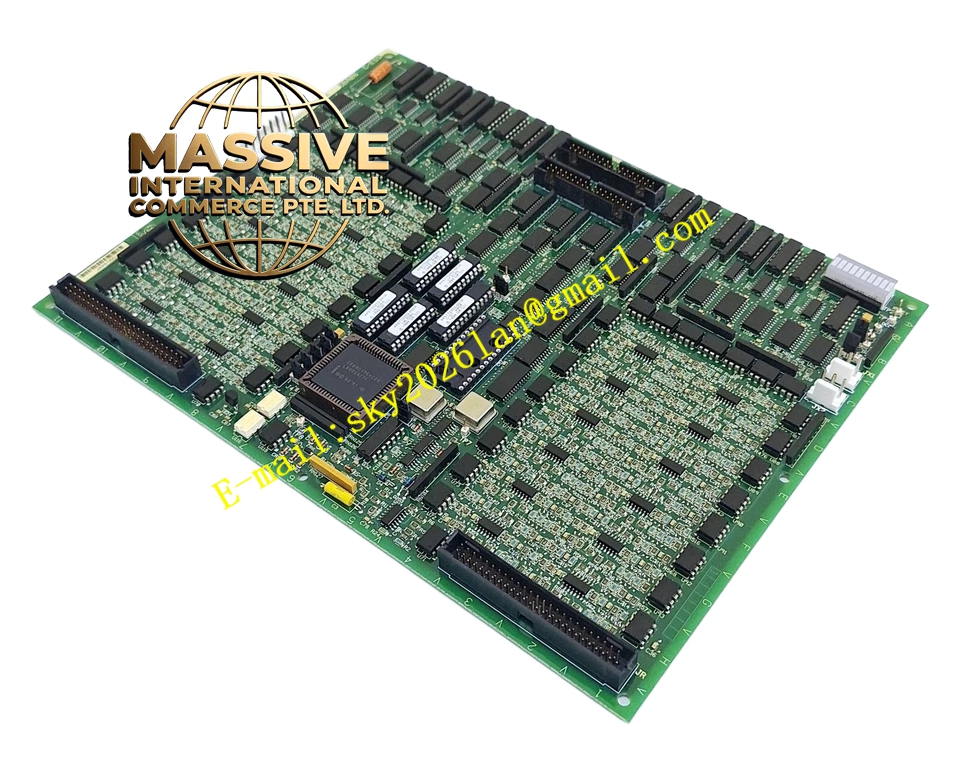
Description
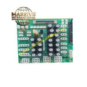
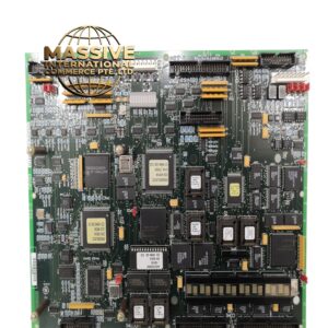
GE DS200TCDAH1BHE
Technical Specifications
- Manufacturer: General Electric (GE).
- Product Series: Mark V Gas Turbine Control System.
- Board Type: RST Analog I/O Board (TCQA).
- Origin: United States.
- Connectors: 2PL, 3PL, JE, JF, JG, JA, JB, JD, JBR, JFR, JGR.
Functional Features
- Signal Conditioning: Scales and conditions LVDT inputs, servo valve outputs, thermocouple inputs, 4-20 mA inputs/outputs, vibration inputs, relay driver outputs, pulse inputs, and voltage inputs.
- Data Bus Communication: Transmits conditioned signals to the COREBUS via the 3PL connector, linking STCA, TCQA, and TCQE boards.
- Generator & Line Signals: Utilizes the JE connector to send and receive generator and line signals to and from the TCQC board.
- Hardware Configuration: Features hardware jumpers J1 and J2 for selecting milliamp output circuits, and J5/J6 for configuring output current ranges (20 mA or 200 mA). J7 is used for RS232 card testing, and J8 starts the oscillator.
Application Scenarios
Primarily deployed in power generation facilities utilizing GE gas turbines, specifically for monitoring compressor stall detection, fuel flow pressure, and various generator parameters.
Performance Parameters
- Signal Types Handled: 4-20 mA, +/- 10 V DC, LVDT/LVDR position inputs, and thermocouple signals.
- Cold End Compensation: Supported via JA connector on TBQA board for thermocouple inputs.
Material Composition
Constructed with high-reliability industrial-grade electronic components, multi-layer printed circuit boards, and precision hardware jumpers for robust signal processing.
Structural Characteristics
Standard Mark V I/O core board form factor featuring multiple specialized connectors (2PL, 3PL, JE, etc.) for interfacing with terminal boards (TBQA, TBQC, TBQB) and other core boards (STCA, TCQC, TCTG).
Operating Principle
The board receives raw analog signals from field devices via terminal boards, scales and conditions these signals internally, and routes the processed data to the system’s core processor via the 3PL data bus for real-time turbine control and protection logic.
Installation Requirements
Must be securely installed in the designated I/O core slot. Ensure all associated terminal boards (TBQA, TBQC) are properly wired and that hardware jumpers (J1, J2, J5, J6) are set according to the specific system configuration requirements.
Usage Precautions
Always refer to the hardware jumper panel in Appendix A and the operator interface before modifying jumper settings. Ensure proper grounding and ESD protection during handling to prevent damage to sensitive analog conditioning circuits.