Description
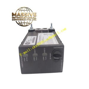
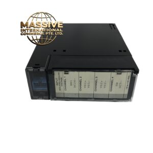
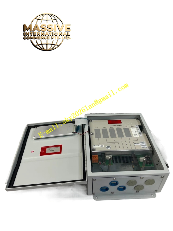
GE GM868-2-11-10045-S
- Technical Specifications:
- Pipe Size: 2 in to 120 in (50 mm to 3000 mm)
- Flow Velocity Range: -150 to +150 ft/s (-46 to 46 m/s) bidirectional
- Accuracy: ±1% to 2% of reading (typical), ±0.5% with process calibration
- Repeatability: ±0.2% to 0.5% of reading
- Power: 100–240 V AC or 12–28 V DC, 20 W max
- Fluid Types: All acoustically conductive gases
- Functional Features: Transit-time measurement principle; one or two measurement paths; optional dual-channel for two pipes; infrared keypad; optional backlit LCD; Class I Div 1 flameproof enclosure options; built-in diagnostics for signal quality.
- Application Scenarios: Natural gas custody transfer, compressed air system monitoring, flue gas flow in power plants, biogas production facilities, chemical plant gas distribution.
- Performance Parameters: Rangeability 1500:1; response time 3 seconds to within 1% of final value; operates on pipes of metal or certain non-metals; requires 20D upstream / 10D downstream straight run (or flow correction).
- Material Composition: Electronics enclosure in epoxy-coated aluminum (Type 4X/IP66) or stainless steel; transducers in stainless steel with piezoelectric crystals; armored RG62 coaxial cable with shielding.
- Structural Features: Wall-mount or pole-mount electronics housing; separate transducer clamps with mounting fixtures; cable glands for sealed entry; DIP switches or menu-driven setup; expansion slots for option cards (analog output, etc.).
- Working Principle: Paired transducers mounted on the pipe exterior send ultrasonic pulses alternately upstream and downstream; the time difference (transit-time) between these pulses is proportional to the gas velocity, which is combined with pipe cross-sectional area to calculate volumetric or mass flow.
- Installation Requirements: Clean pipe surface at transducer mounting locations to ensure acoustic coupling (use couplant); mount transducers opposite each other or in Z-path/V-path per pipe diameter; ensure minimum straight run or apply profile correction factors; ground enclosure and shield properly.
- Usage Precautions: Avoid installing near excessive noise sources (valves, pumps) that interfere with ultrasound; verify gas composition/acoustic conductivity; reapply couplant if reinstalling transducers; protect cables from physical damage and UV exposure if outdoors.