Description
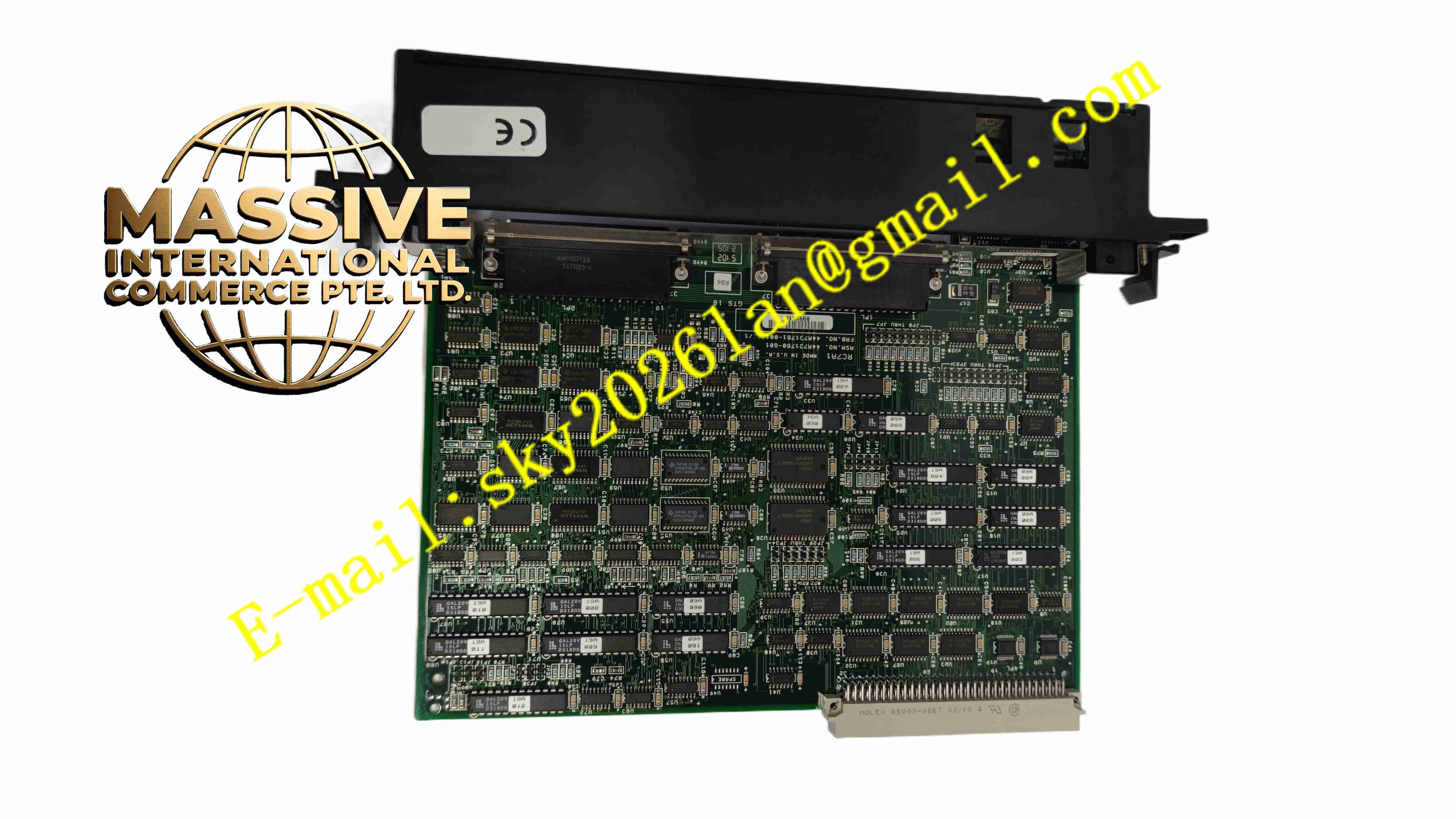
GE IC697RCM711 Redundancy Communications Module
Technical Specifications
- Brand: GE Fanuc
- Model: IC697RCM711
- Product Type: Redundancy Communications Module
- System Platform: Series 90-70 PLC
- Function: CPU-to-CPU redundancy communication and synchronization
- Redundancy Support: Hot-standby and enhanced hot-standby CPU redundancy
- Installation Location: Rack 0 of each redundant CPU
- Slot Requirement: Installed in both primary and secondary PLCs
- Communication Link: Dedicated redundancy communications link between CPUs
- Status Indicators: OK, Local Ready, Local Active, Remote Ready, Remote Active, and Redundancy LEDs
- Unit Select Pushbutton: Manual switchover from active to backup CPU
- Configuration: Software configured through Series 90-70 programming software
- Product Status: Discontinued by manufacturer
Functional Features
- Redundant CPU Synchronization: Keeps the backup CPU aligned with the active CPU.
- Hot-Standby Support: Allows seamless switchover during CPU failure.
- Data Sharing: Transfers I/O data, memory data, and status between CPUs.
- Manual Switchover: Pushbutton allows controlled transfer of control to the backup unit.
- Program-Controlled Switchover: Switchover can also be initiated through SVC_REQ functions.
- Status Diagnostics: LEDs show local and remote CPU readiness and active status.
- High-Speed Link: Provides fast communication between redundant CPUs.
- Software Configuration: No DIP switches; configured in PLC software.
Application Scenarios
- Critical process control systems
- Power generation and utility control
- Oil and gas pipeline control
- Continuous manufacturing lines
- Water and wastewater treatment plants
- Safety-critical automation systems
- Systems requiring high availability and fault tolerance
- Retrofit and maintenance of Series 90-70 redundant PLC systems
Performance Parameters
- Switchover Capability: Supports automatic and manual CPU switchover.
- Synchronization Speed: High-speed link for real-time CPU data sharing.
- Diagnostic Coverage: Local and remote status visible through module LEDs.
- Reliability: Designed for continuous operation in redundant control systems.
- Integration: Works with Series 90-70 hot-standby and enhanced hot-standby CPUs.
- Maintenance Support: Allows controlled testing and switchover during service.
Material Composition
- Module Housing: Industrial-grade plastic enclosure.
- PCB: Communication and synchronization control board.
- Redundancy Interface: Dedicated link circuitry for CPU-to-CPU communication.
- Backplane Connector: Interfaces with the Series 90-70 rack bus.
- Status LEDs: Indicate module health, local status, and remote status.
- Pushbutton Switch: Manual unit-select switch for CPU switchover.
- Communication Ports: Connect to the redundancy link between primary and secondary PLCs.
Structural Features
- Single-Slot Module: Fits into a Series 90-70 PLC rack.
- Front-Panel LEDs: Provide clear redundancy and CPU status indication.
- Unit Select Pushbutton: Allows manual switchover without external tools.
- Redundancy Communication Ports: Connect primary and secondary PLCs.
- Robust Backplane Interface: Ensures reliable communication with the CPU.
- Compact Industrial Design: Fits standard Series 90-70 rack 0 installations.
Working Principle
In a redundant Series 90-70 system, the active CPU controls all I/O while the backup CPU remains synchronized. The IC697RCM711 provides the communication path that transfers I/O data, memory images, and status information between the two CPUs. If the active CPU fails, the backup CPU takes control with minimal disruption. The module also allows operators to manually switch control using the front-panel pushbutton or through program logic. Status LEDs show whether each CPU is ready, active, or in fault.
Installation Requirements
- Install one IC697RCM711 in the primary PLC and one in the secondary PLC.
- Place the module in rack 0 of each redundant CPU.
- Ensure no empty slot exists between the CPU and the RCM unless other required modules are present.
- Connect the redundancy communication cable between the two RCM modules.
- Verify cable length and termination requirements before commissioning.
- Configure redundancy parameters in the Series 90-70 programming software.
- Test local and remote status LEDs before placing the system into automatic redundancy.
- Perform controlled switchover testing during commissioning.
Precautions for Use
- Do not install the RCM in only one CPU; both CPUs require the module.
- Do not change redundancy wiring while the system is in critical operation.
- Verify that the backup CPU is READY before manual switchover.
- Wait at least 10 seconds between manual switchover requests.
- Do not remove the module during active redundancy operation.
- Keep redundancy configuration backups before maintenance.
- Replace failed modules with the same IC697RCM711 model.
- Only qualified PLC engineers should configure or service redundant systems.
- Refer to the official GE Fanuc Series 90-70 redundancy documentation for exact wiring and configuration.