Description
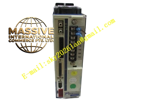
Kollmorgen CR03251
- Technical Specifications
- Input Power: Single‑phase 115 / 230 VAC, 47‑63 Hz
- Rated Continuous Output Current: 1.2 A RMS
- Peak Output Current: 6 A RMS (0.5 second duration)
- Apparent Power Rating: 0.35 kVA at 115 VAC, 0.8 kVA at 230 VAC
- Auxiliary Logic Supply: 22‑27 VDC
- Analog Monitoring Output: ±10 V, 12‑bit resolution
- Cooling Method: Natural convection aluminum heat sink
- Protection Class: IP20
- Weight: 2.1 kg
- Functional Features
- Analog velocity‑loop and current‑loop control circuit with digital fault diagnosis
- Supports torque mode, velocity mode and external step‑direction position reference
- 12‑bit analog monitoring output for real‑time motion status observation
- Hardware protection functions: over‑current, over‑voltage, under‑voltage, short‑circuit, heat‑sink overtemperature, feedback‑signal loss detection
- Open‑collector fault signal output, fault contact closing time 3 ms
- Panel‑mount trimming potentiometers for current‑loop gain, velocity‑loop gain, offset adjustment
- Integrated dynamic braking circuit for fast motor deceleration
- No built‑in fieldbus communication interface
- Application Scenarios: Small‑format legacy automated positioning tables, laboratory test‑equipment axes, miniature packaging auxiliary drives, old‑model semiconductor handling equipment, low‑power retrofitting projects
- Performance Parameters: Velocity‑loop bandwidth reaches 320 Hz; current‑loop hardware response time below 12 µs; analog command resolution 4.9 mV; compatible with DC tachometer and incremental encoder feedback signals
- Material Composition: Anodized aluminum extrusion heat sink, cold‑rolled steel sheet metal housing, FR‑4 printed circuit boards, bipolar power output transistors, electrolytic power capacitors, plastic barrier terminal blocks, carbon‑film trimming potentiometers
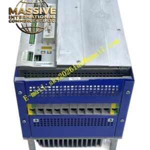
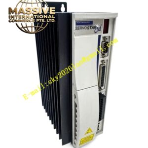
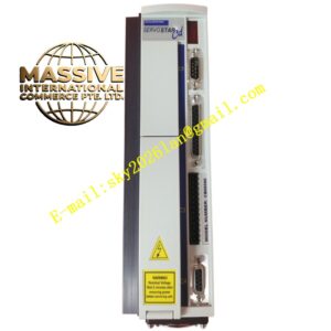
- Structural Characteristics: Compact horizontal panel‑mount housing; internal physical separation for high‑power power region and low‑level signal region; barrier screw terminals for power and logic‑signal wiring; D‑Sub feedback connector; top‑side access cover for gain potentiometer adjustment; four corner mounting holes for cabinet‑panel installation.
- Working Principle: Input AC mains passes through rectifier circuit to generate DC‑bus voltage; analog comparator amplifies deviation between external command signal and motor feedback signal; power output stage outputs adjustable DC drive current to brush‑type servo motor; tachometer or encoder feeds real‑time velocity and position feedback back to control circuit; fault‑monitoring hardware continuously detects operating status, triggers fault output and disables power‑stage output once fault condition appears.
- Installation Requirements: Horizontal panel‑mount installation inside control cabinet; keep surrounding clearance for natural convection heat dissipation; connect protective‑earth terminal reliably to cabinet ground bus; operating ambient temperature 0‑40 °C; no performance derating below 1000 m altitude.
- Usage Notes: Complete protective‑earth wiring before power‑on; never energize without valid motor‑load connection; fine‑tune loop gain potentiometers incrementally to eliminate mechanical resonance; perform capacitor reforming when unit storage time exceeds 12 months; prevent condensation and conductive‑dust ingress; keep enclosure cover closed during running operation; double‑check feedback wiring before commissioning.