Description
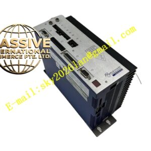
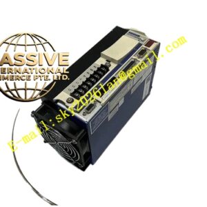
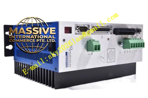
Kollmorgen S70302‑NANAF2
- Technical Specifications
- Input Power: 3‑phase 208‑480 VAC, 50‑60 Hz grounded TN / TT industrial power grid
- Rated Continuous Output Current: 3 A RMS
- Peak Output Current: 9 A RMS (2‑second duration)
- Rated Apparent Power S1 Operation: 2.2 kVA
- DC‑link Voltage: 290‑675 VDC
- Auxiliary Supply: 24 VDC isolated control power
- Cooling Method: Passive aluminum base heat sink plus slot‑3 mounted F2 controlled forced‑air fan module
- Protection Class: IP20
- Weight: 4.4 kg
- Expansion Slot Assignment: Slot 1‑NA, Slot 2‑NA, Slot 3‑F2 fan module
- Functional Features
- Onboard native EtherCAT and CANopen communication, RS232 diagnostic service interface
- Multi‑feedback universal compatibility: resolver, SFD3, Hiperface‑DSL, incremental encoder, Aquad‑B encoder
- MMC memory card slot for parameter backup, drive cloning and on‑site firmware upgrade
- Dual‑channel STO Safe Torque‑Off safety function, SIL 2 / PLd safety rating
- Integrated auto‑tuning algorithm, cogging‑torque suppression, high‑dynamic multi‑loop motion control
- IEC 61131 macro programming runtime for custom motion‑logic sequence execution
- Vacant slot 1 and slot 2 support later installation of fieldbus adapter or position‑I/O expansion cards
- Slot‑3‑mounted F2 fan module delivers active forced‑air cooling for sustained cyclic‑load operation
- Application Scenarios: Small automated assembly equipment, laboratory test‑stand axes, small‑format packaging machinery, printing auxiliary drives, automation machines with special cabinet layout limitation
- Performance Parameters: Current‑loop cycle 62.5 µs, position‑loop cycle 250 µs; supports electronic gearing, cam profile operation, multi‑axis master‑slave synchronization, encoder emulation output, analog set‑point input
- Material Composition: Anodized aluminum heat‑sink housing, galvanized steel mounting bracket, FR‑4 printed circuit boards, IGBT power semiconductor modules, thermoplastic connector housings, F2 brushless fan expansion assembly, blank plastic protective covers for slot 1 and slot 2
- Structural Characteristics: Vertical book‑style cabinet‑mount housing; physical separation of high‑power power compartment and low‑voltage control compartment; combicon power terminals, D‑Sub feedback and signal connectors; three front‑side expansion slots; F2 fan module mechanically locked within slot 3; slot 1 and slot 2 covered by blank protective panels.
- Working Principle: Three‑phase AC input converted to DC‑link bus voltage by input rectifier; DSP motion controller executes real‑time current‑speed‑position closed‑loop algorithm; PWM power inverter outputs variable‑frequency three‑phase AC to drive servo motor; motor encoder feeds position‑speed feedback signal back to DSP to close control loops; dual‑channel redundant STO hardware cuts power‑stage output upon safety‑related machine trigger events; slot‑3‑installed F2 fan module generates directional airflow to remove heat accumulated on power‑semiconductor surfaces.
- Installation Requirements: Vertical upright mounting inside control cabinet; preserve sufficient vertical ventilation gap above and below amplifier unit; mounting surface must be conductive metal plate for reliable EMC grounding; operating ambient temperature 0‑45 °C with F2 fan module fitted; apply 1.5 % performance derating per 100 m elevation when altitude exceeds 1000 m.
- Usage Notes: Protective earth connection must be securely fastened before power‑on; 24 VDC auxiliary supply must maintain galvanic isolation; F2 fan module cannot be plugged or unplugged under powered condition; MMC memory card hot‑swap is forbidden during drive running state; verify motor inductance and feedback parameters during commissioning phase; strictly comply with EMC wiring specification; avoid condensation, corrosive gas and heavy‑dust surroundings; conduct periodic visual inspection for fan inlet dust clogging.