Description
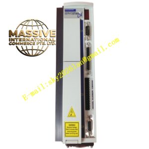
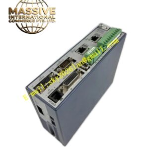
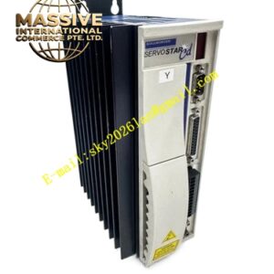
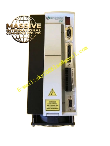
Kollmorgen S7240S‑NANAF2
- Technical Specifications
- Input Power: 3‑phase 208‑480 VAC, 50‑60 Hz grounded industrial power grid
- Rated Continuous Output Current: 24 A RMS
- Peak Output Current: 72 A RMS (2‑second duration)
- Rated Apparent Power S1 Operation: 18 kVA
- DC‑link Voltage: 290‑675 VDC
- Auxiliary Supply: 24 VDC isolated control power
- Cooling Method: Passive large‑area aluminum heat sink plus slot‑3 mounted F2 controlled forced‑air fan module
- Protection Class: IP20
- Weight: 5.5 kg
- Expansion Slot Assignment: Slot 1‑NA, Slot 2‑NA, Slot 3‑F2 fan module
- Functional Features
- Onboard native EtherCAT and CANopen communication interfaces, RS232 diagnostic service port
- Universal multi‑feedback support: resolver, SFD3, Hiperface‑DSL, incremental encoder, Aquad‑B encoder
- MMC memory card slot for parameter backup, drive cloning and on‑site firmware upgrade
- Dual‑channel STO Safe Torque‑Off safety function, SIL 2 / PLd safety rating
- S‑variant enhanced power stage hardware delivers maximum peak‑current capacity for heavy short‑term shock‑load motion
- Built‑in auto‑tuning, cogging‑torque suppression algorithm, high‑speed multi‑loop closed‑loop motion control
- IEC 61131 macro programming runtime for complex custom motion‑logic execution
- Vacant slot 1 and slot 2 support later installation of fieldbus adapter or position‑I/O expansion hardware
- Slot‑3‑mounted F2 fan module provides powerful forced‑air cooling to dissipate heat generated by frequent heavy‑overload cycles
- Application Scenarios: High‑force press auxiliary axes, heavy‑duty high‑acceleration gantries, metal forming automation, large pick‑and‑place equipment, heavy‑duty converting machinery with special cabinet layout restrictions
- Performance Parameters: Current‑loop cycle 62.5 µs, position‑loop cycle 250 µs; supports electronic gearing, cam profile operation, multi‑axis master‑slave synchronization, encoder emulation output, analog set‑point input
- Material Composition: Oversized anodized aluminum heat‑sink housing, galvanized steel heavy‑duty mounting bracket, FR‑4 high‑temperature grade printed circuit boards, high‑current enhanced‑rating IGBT power modules, heavy‑duty combicon power terminals, thermoplastic connector housings, F2 brushless fan expansion assembly, blank plastic protective covers for slot 1 and slot 2
- Structural Characteristics: Vertical book‑style cabinet‑mount construction; physical isolation between high‑power power compartment and low‑voltage signal control compartment; heavy‑current combicon power terminals, D‑Sub feedback and signal connectors; three front‑facing expansion slots; F2 fan module mechanically locked inside slot 3; slot 1 and slot 2 fitted with blank protective panels.
- Working Principle: Three‑phase AC mains input passes through full‑bridge rectifier to establish stable high‑voltage DC‑link bus; high‑performance floating‑point DSP controller executes ultra‑fast multi‑layer closed‑loop control algorithm; enhanced‑rating PWM power inverter outputs high‑amplitude short‑duration peak‑current three‑phase AC to drive high‑inertia heavy‑shock‑load servo motor; motor encoder feeds real‑time position‑velocity feedback signal back to DSP for loop closure; dual‑channel redundant STO hardware immediately disables power‑stage output upon safety trigger events; slot‑3‑installed F2 fan module generates directional airflow to remove massive heat from power semiconductors caused by repeated heavy‑overload operation.
- Installation Requirements: Vertical upright mounting inside heavy‑duty control cabinet; maintain enlarged vertical ventilation clearance above and below amplifier unit; mounting surface must be conductive metal plate for reliable EMC grounding; operating ambient temperature range 0‑45 °C with F2 fan module installed; performance derating 1.5 % per 100 m elevation when altitude exceeds 1000 m.
- Usage Notes: Secure heavy‑duty protective earth connection before applying main power; 24 VDC auxiliary control supply must maintain full galvanic isolation; F2 fan module cannot be inserted or removed while drive remains powered; MMC memory‑card hot‑swap is strictly prohibited during drive running state; complete high‑power motor parameter matching and feedback calibration during commissioning; strictly observe EMC wiring specifications; avoid condensation, corrosive gas and conductive‑dust environment; carry out regular visual inspection and dust removal for fan inlet grille.