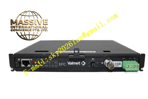
Description
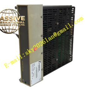
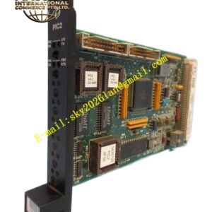
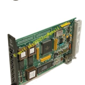
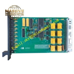
METSO D200175
Technical Specifications: DIN rail mounting structure; 24VDC rated working voltage; terminal block supports wire cross-section from 0.5mm² to 1.5mm²; built-in surge suppression components; operating temperature range -20℃ to +70℃; protection class IP20; matched with corresponding IOP series module cards.
Functional Features: Centralized wiring for field input and output signals; built-in surge protection to absorb instantaneous overvoltage from long-distance cables; integrated short-circuit protection circuit; terminal marking printed on housing for quick identification; mechanical locking structure for upper I/O module; independent shielding grounding terminals for signal cables.
Application Scenarios: DCS control cabinet in pulp and paper manufacturing plant; auxiliary control cabinet of thermal power station; safety interlock cabinet of chemical process plant; automation control cabinet of mineral processing plant; water treatment plant process signal wiring cabinet.
Performance Parameters: Stable terminal contact resistance; low temperature rise under long-term continuous load; fast response speed of surge protection components; fully comply with industrial EMC electromagnetic compatibility standards; support 7×24 hours uninterrupted continuous operation.
Material Composition: Flame-retardant high-temperature engineering plastic shell; copper alloy gold-plated wiring terminals; glass fiber epoxy insulating substrate; metal DIN rail fixing buckle.
Structural Features: Long strip shape designed for standard DIN rail installation; housing is divided into signal terminal area and grounding terminal area; upper card slot for vertical insertion of matching IOP module; internal dip switch for terminal resistance switching; housing engraved with complete terminal definition marks.
Working Principle: Field sensor and actuator cables are connected to the terminal block of D200175 base. The signal is transmitted to the I/O module inserted above the base through internal circuit. The built-in surge protection device absorbs transient high voltage induced by field cables. The shielding wire of signal cable is connected to the dedicated grounding terminal of the base to reduce electromagnetic interference.
Installation Requirements: Clamp the base firmly on the DIN rail inside the control cabinet without offset or loosening. Use shielded twisted cables for field signal wiring. The shielding layer of signal cable adopts single-point grounding. Signal cables and high-power power cables are laid in separate trunking. Connect the grounding terminal of the base to the cabinet protective ground reliably.
Precautions for Use: Cut off the power supply of field loop before wiring operation. Strictly follow the terminal definition drawing to avoid wrong connection of power line and signal line. Do not introduce high voltage signal into signal terminals. Check the tightness of wiring terminals regularly. Keep the terminal area clean and prevent dust accumulation leading to insulation degradation.