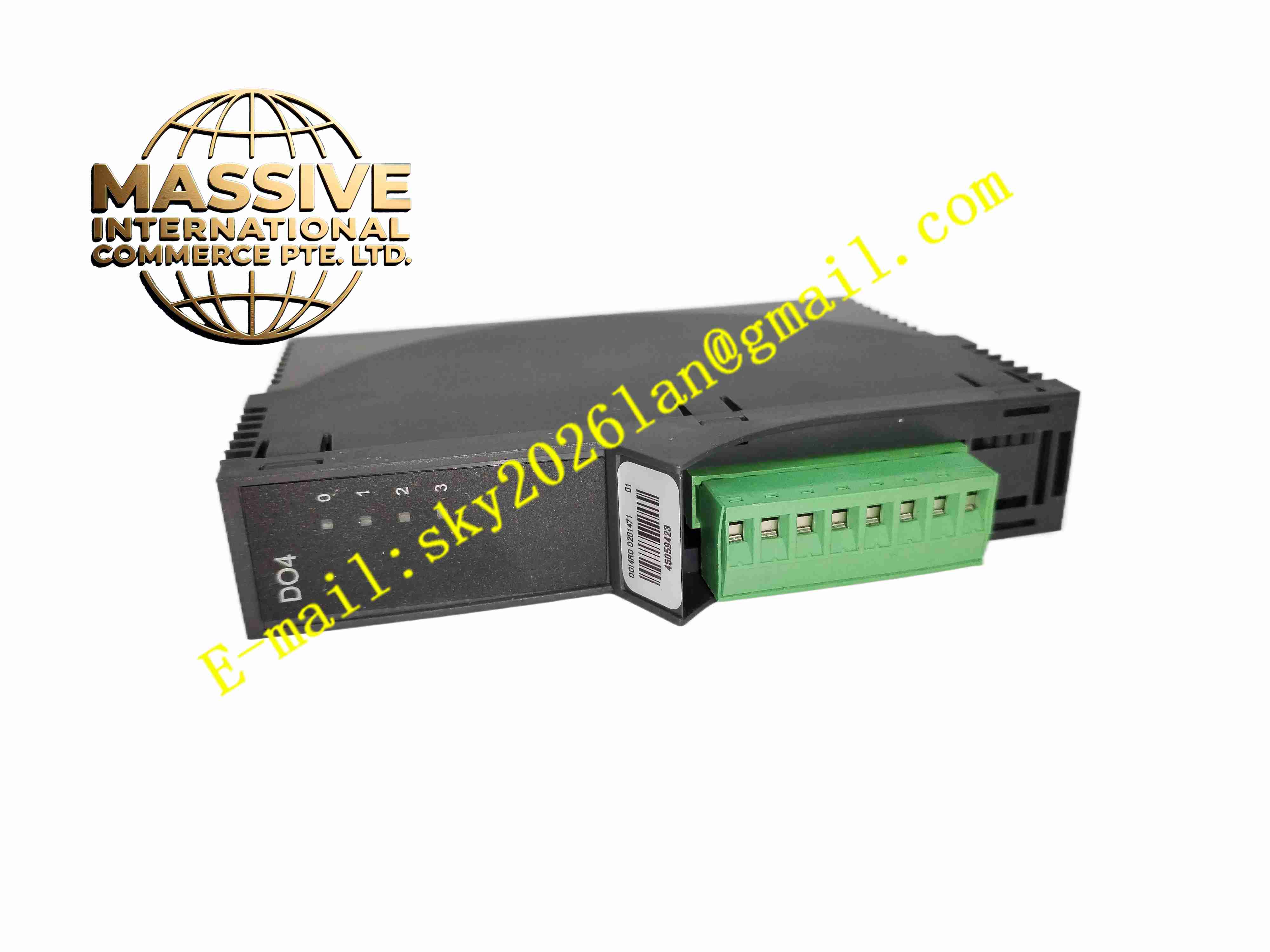
Description
Metso D201471
Technical Specifications Output signal range 4-20 mA analogue current; channel isolation between output channels and rack backplane bus; rack 28 V DC backplane power supply; operating temperature -20 ℃ to +70 ℃; uncoated FR4 PCB; rack plug-in compatible with Metso MAX backplane; per-channel fault and status LED; output short-circuit protection.
Functional Features High-precision digital-to-analogue conversion for process setpoint generation; configurable output scaling and loss-of-communication fail-safe value; per-channel short-circuit protection; loop fault diagnostic detection; front panel LED to display channel active or fault state; output value update synchronised with DCS control cycle.
Application Scenarios Central control room control valve positioning output, water treatment chemical dosing actuator command, power plant auxiliary valve analogue regulation, clean-environment pulp mill central control racks.
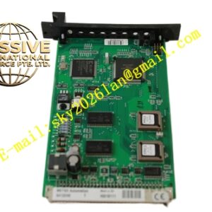
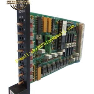
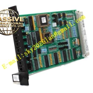
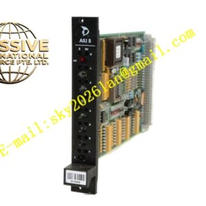
Material Composition Flame-retardant plastic module housing; uncoated FR4 analogue output PCB; precision DAC and analogue driver circuits; current sensing resistors; gold-plated backplane edge connector; removable screw terminal blocks for field actuator wiring.
Structural Characteristics Rack plug-in mechanical design; front panel with channel status LEDs and removable field terminal block; rear edge gold finger mates with Metso MAX rack backplane; analogue output circuits isolated from rack digital control logic.
Working Principle Rack CPU sends digital setpoint value to the module via rack backplane bus. Digital values are loaded into DAC chips. Analogue driver circuits generate proportional 4-20 mA current for field control loops. Current monitoring circuits detect short or open loops and report fault status back to the DCS controller. Predefined fail-safe output activates during communication loss.
Installation Requirements Install module in unpowered Metso MAX rack; wire field valve actuators to output terminals; configure scaling and fail-safe parameters in DCS engineering station; check loop resistance to match module drive capability.
Operation Notes Calibrate 4 mA zero and 20 mA full scale after module replacement; confirm actuator response after parameter modification; avoid exposure of uncoated PCB to condensation and corrosive vapour.