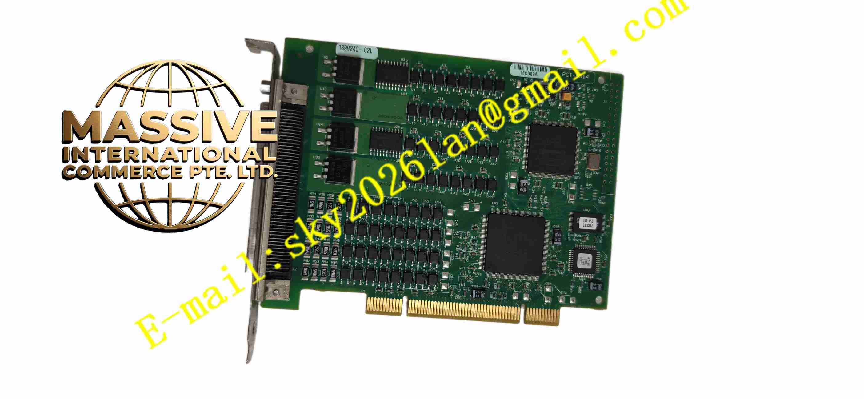
Description
NI PCI-6514
Technical Specifications: Bus interface: Standard PCI bus Digital input channels:32 sink/source digital input channels Digital output channels:32 source digital output channels Total channels:64 digital I/O channels Channel grouping:8 isolated banks Input voltage range:±30 VDC Output maximum current:75 mA per single channel Digital filter: Software configurable input debounce filter Watchdog: Digital I/O watchdog for fault safety state Power supply: PCI bus power supply for board logic; external field power for output loads Operating temperature range:0℃ ~ +55℃ Storage temperature range:-40℃ ~ +85℃ Relative humidity:5% to 90%, non-condensing Connector:100-pin D-SUB connector Form factor: Full-height PCI add-on card Protection grade:IP20
Functional Features: Eight independent isolated banks prevent fault in one bank from affecting other channel groups. 32 bidirectional sink/source digital input channels read switch, relay auxiliary contact and proximity sensor status. 32 source digital output channels drive relays, solenoid valves and indicator lamps. Programmable power-on output state defines safe output level immediately after power recovery. Digital watchdog automatically switches outputs to preset safe state when software or PC crash occurs. Software-selectable digital input filter eliminates signal glitches and realizes switch signal debouncing. NI-DAQmx driver support for LabVIEW and text-based programming languages. Front panel LED indicators show board power and communication operating state. Power-on self-test detects internal hardware fault after power energization.
Application Scenarios: Automated production line discrete signal control, relay cabinet status monitoring, packaging machine I/O control, conveyor system sensor signal collection, safety interlock signal acquisition, test bench relay switching control, material handling equipment logic control.
Performance Parameters: Fast response speed for digital input state change capture. Isolation circuit suppresses high voltage transient spikes generated by inductive loads. Watchdog function reliably triggers safety state within fixed response time upon system failure. Continuous stable channel operation under rated current and voltage load condition. Long service life for repeated high-speed switching cycles.
Material Composition: PCB substrate: Multi-layer FR4 glass fiber epoxy printed circuit board. Core components: Digital logic FPGA, optocoupler isolation chips, surge suppression diode array, output power driver IC, PCI interface chip. Mechanical part: Steel full-height PCI mounting bracket. Connector: Metal shielded 100-pin D-SUB connector with gold-plated contact pins.
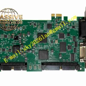
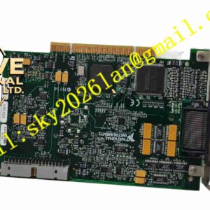
Structural Features: Standard full-height PCI plug-in card form factor for standard industrial PC PCI slot. Steel rear bracket fitted with 100-pin high-density D-SUB connector for field I/O wiring. Internal circuit divided into PCI bus logic region and eight independent isolated field banks. Each bank has independent optocoupler isolation circuit to separate PC circuit and field wiring. Gold-plated PCI edge connector inserts into PCI slot for data and power transmission.
Working Principle: PCI-6514 obtains logic power supply from PCI bus after being installed in PC PCI slot. NI-DAQmx driver initializes FPGA logic and channel configuration. Field digital input signals pass through optocoupler isolation circuit and surge protection components before entering FPGA. FPGA reads on/off status of each input channel and transmits status data to host PC through PCI bus. When host software sends output control commands, FPGA activates corresponding source output drivers to switch external 24V field power to connected loads. If software crash or PC fault happens, watchdog timer triggers automatically and sets all outputs to predefined safe state. Software configurable filter removes transient noise pulses on input signals.
Installation Requirements: Power off host PC before inserting PCI-6514 digital I/O board. Insert card into free PCI slot and fasten steel bracket mounting screw. Connect shielded 100-core cable from D-SUB connector to external terminal block module. Install NI-DAQmx driver software on host computer. Configure channel bank mode, power-up state and watchdog safety parameters inside project software. Connect field sensors and solenoid loads to terminal block with external 24VDC field power. Ground industrial PC chassis to reliable protective earth point. Separate field I/O signal cables from high-power motor cables.
Usage Notes: Use freewheeling diodes when driving inductive loads such as solenoid valves and relays. Do not exceed maximum rated output current of each digital output channel. Wear anti-static wristband when handling the PCI card. Backup project configuration before modifying watchdog or output parameters. Do not apply voltage exceeding ±30V to digital input terminals. Do not operate card outside rated temperature and humidity range. Inspect terminal block screw tightness periodically.