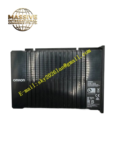
Description
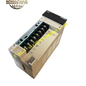
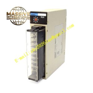
OMRON CJ1W‑ID211
Technical Specifications: Total input points: 16 points; rated input voltage DC24V; allowable input voltage range DC19.2‑28.8V; typical input current per channel 7 mA; ON‑state threshold minimum DC14.4V; OFF‑state threshold maximum DC5V; maximum response‑on time 8 ms; maximum response‑off time 8 ms; optocoupler isolation between field circuit and PLC internal logic circuit; dielectric strength 1000 VAC for 1 minute between external terminals and ground; internal current consumption 80 mA at DC5V; operating temperature 0‑55°C; storage temperature ‑20‑75°C; operating humidity 10‑90%RH without condensation; weight 110 g; removable screw terminal block; LED status indicator for each channel.
Functional Features: 16‑channel DC24V digital signal acquisition; built‑in optocoupler isolation prevents field surge noise from damaging PLC internal hardware; independent LED indicator for every input channel for direct on‑site signal status observation; grouped common‑terminal layout reduces field wiring workload; fully compatible with CJ‑series backplane bus architecture.
Application Scenarios: Automated production‑line digital signal collection; proximity sensor and photoelectric sensor signal acquisition; packaging machinery field switch‑signal input; logistics conveying equipment signal detection; spare‑part replacement for legacy CJ‑series automation installations.
Performance Parameters: Isolation circuit effectively suppresses industrial‑field electrical interference; electromagnetic compatibility performance complies with IEC 61000‑4 series standards; vibration and shock resistance meet cabinet‑mount industrial equipment requirements; support continuous long‑term stable cabinet‑internal operation.
Material Composition: Black V0 flame‑retardant engineering‑plastic housing; internal FR‑4 multilayer glass‑fiber printed‑circuit board; large‑quantity optocoupler isolation chips; brass nickel‑plated removable screw terminal block; gold‑plated backplane edge‑connector contacts; high‑brightness LED channel‑status indicators.
Structural Features: Slim standard CJ‑series rack‑slot physical dimension; gold‑plated edge‑connector on rear surface connects with CJ‑series rack backplane bus; front‑panel removable screw‑type terminal block for field sensor wiring; array of LED indicators corresponding to 16 input channels on front face; side locking clips fasten module into rack‑slot position.
Working Principle: Field DC24V switching signal connects to module screw terminals. When input voltage rises above ON‑state threshold, corresponding‑channel optocoupler turns on and converts field DC signal into internal logic‑level signal. Matching‑channel front‑panel LED indicator lights up synchronously. Logic status data transfers via internal circuit and rear‑side gold‑plated contacts to CJ‑series CPU for cyclic‑scan reading in user control program. When field‑signal voltage drops below OFF‑level threshold, optocoupler switches off and LED extinguishes.
Installation Requirements: Install CJ1W‑ID211 into idle slot on CJ‑series main rack or expansion rack; secure CJ‑series rack onto cabinet DIN rail; deploy shielded cables for field sensor wiring whenever possible; physically separate sensor‑signal cables from high‑power motor and inverter power cables; implement reliable protective grounding for control cabinet.
Usage Notes: Hot‑swap of this module is strictly forbidden; external input voltage must stay within DC19.2‑28.8V operating range; do not deploy in environments with condensation or corrosive gas; perform periodic inspection of screw‑terminal fastening torque.