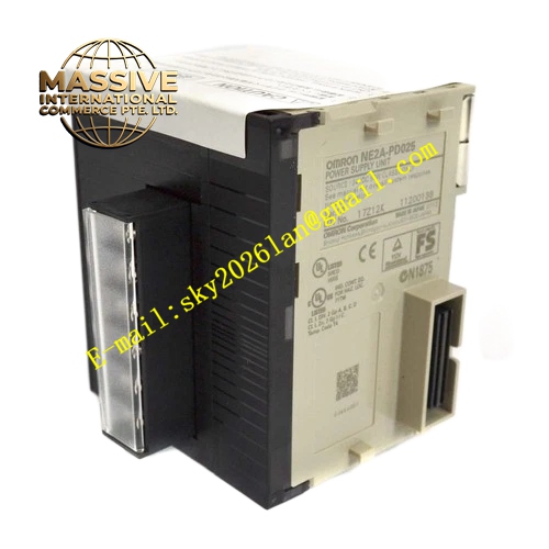
Description
OMRON CJ1W-OC211
Technical Specifications:
- Brand: OMRON
- Model: CJ1W-OC211
- Product Type: Relay Output Unit
- Compatible System: CJ / NJ Series PLC
- Number of Outputs: 16 points
- Output Type: Relay (Form A – Normally Open)
- Switching Capacity:
- 250 VAC, 2 A (Resistive load)
- 24 VDC, 2 A (Resistive load)
- Minimum Load: 1 mA at 5 VDC
- Response Time: 15 ms max.
- Electrical Life: 100,000 operations (at 250 VAC, inductive load)
- Mechanical Life: 20,000,000 operations
- External Connection: Removable terminal block
- Power Consumption: 110 mA max. at 5 VDC
- Dimensions: 31 mm (W) × 90 mm (H) × 89 mm (D)
Functional Features:
- 16 points of relay output
- Capable of switching both AC and DC loads
- Removable terminal block for easy wiring
- LED indicators for output status
- Galvanic isolation between outputs and internal circuit
Application Scenarios:
- Controlling solenoids and valves
- Indicator lamp control
- Contactor control for motors
- General purpose switching
- Alarm output
Performance Parameters:
- Output Points: 16
- Output Type: Relay
- Max Switching Capacity: 2 A at 250 VAC / 24 VDC
- Response Time: 15 ms max.
Material Composition:
- Electromechanical relays
- Multi-layer printed circuit board
- Plastic housing
- Removable terminal block
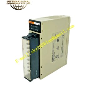
Structural Features: The unit features a compact 31mm width with a removable terminal block. The front panel displays LED indicators for each output point.
Working Principle: The PLC CPU sends digital signals to the unit, which energizes the internal relays. When a relay is energized, its contacts close, completing the circuit for the external load.
Installation Requirements:
- Mount on CJ series CPU rack or expansion rack
- Connect load wiring to the removable terminal block
- Ensure proper ventilation for heat dissipation
- Use surge absorbers for inductive loads
Usage Notes:
- Do not exceed the maximum switching capacity (2 A).
- Relay outputs have a limited mechanical life; consider transistor outputs for high-speed switching.
- Ensure the load voltage matches the relay rating.