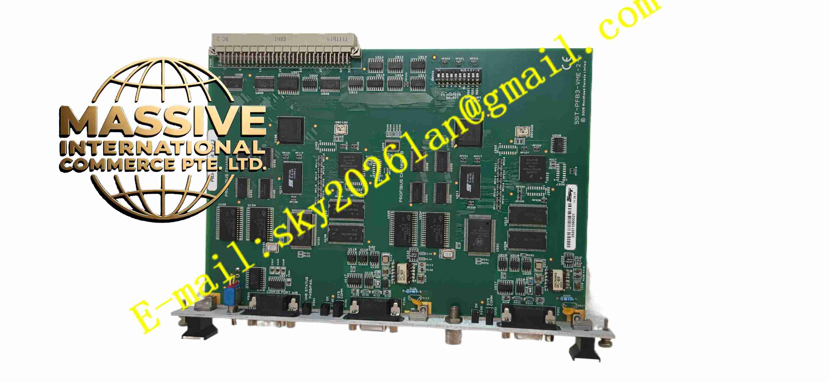
Description
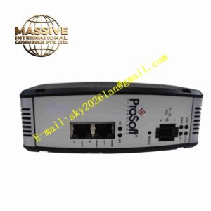
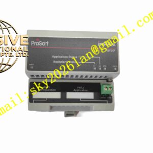
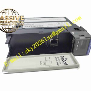
ProSoft SST-PB3-VME-2-E
Technical Specifications VME bus interface; PROFIBUS-DP protocol support; Supports master and slave operation mode; Onboard RAM for data buffer; Operating temperature 0°C to +60°C; D-Sub PROFIBUS connector; VME standard card form factor.
Functional Features Independent PROFIBUS protocol processing reduces host CPU load; Real-time cyclic data exchange with PROFIBUS slave devices; Non-cyclic acyclic parameter access; Onboard diagnostic function for bus and module status; Hot swap support in qualified VME chassis; LED status indicators for bus and power.
Application Scenarios VME based industrial control computer system; Factory automation PROFIBUS network; Power plant VME control rack; Heavy machinery control system; Metallurgical process control equipment; Legacy industrial VME platform fieldbus upgrade.
Performance Parameters PROFIBUS data cycle transmission stable; VME bus data read and write speed consistent; Bus error diagnosis response fast; Onboard data buffer maintains data integrity; Communication immunity to industrial electromagnetic interference.
Material Composition FR4 multi-layer printed circuit board; Bus communication processor; PROFIBUS transceiver chip; Onboard SRAM memory; VME gold-plated edge connector; D-Sub metal connector; LED status indicators; Conformal coating option.
Structural Features Standard 6U VME card size; Gold-plated VME edge connector for backplane connection; Front panel D-Sub connector for PROFIBUS cable; Front panel LED indicators; Metal front panel with mounting bracket for VME chassis.
Working Principle The module plugs into VME chassis slot and communicates with host controller over VME backplane. Onboard processor runs PROFIBUS-DP protocol stack. It exchanges cyclic input and output data with all PROFIBUS slave nodes on fieldbus. Process data received from field devices transfers to VME host memory, and control data from VME host transmits to fieldbus slaves. Module monitors bus communication quality and reports fault status to host system.
Installation Requirements Insert card into standard 6U VME chassis slot and fasten front panel screws; Use PROFIBUS shielded twisted pair cable; Terminate bus ends with PROFIBUS terminator; Connect chassis protective earth; Separate fieldbus cable from high voltage power wiring.
Precautions for Use Set PROFIBUS station address before power on; Check bus termination resistor installation; Do not exceed maximum PROFIBUS cable length corresponding to baud rate; Perform bus diagnostic after commissioning; Avoid electrostatic discharge to PCB before installation.