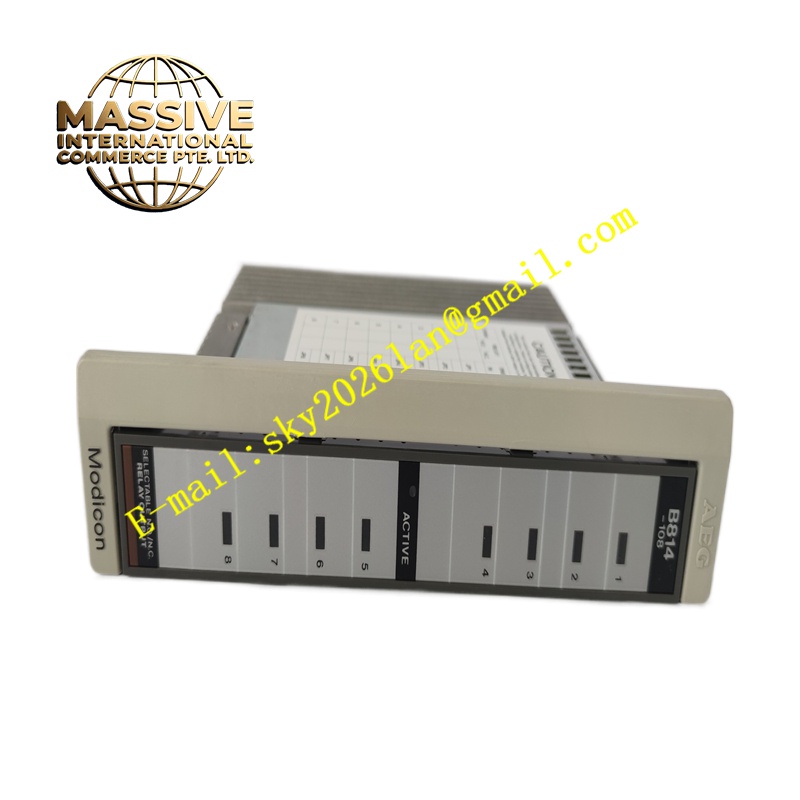
Description
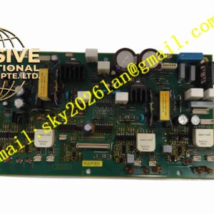
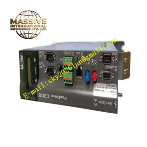
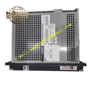
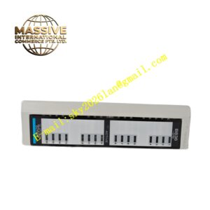
Schneider AS-B814-108
Technical Specifications 8 digital input channels; input rated voltage 24V DC; opto-isolation design for each channel; isolation withstand voltage 1500V AC; supports sinking and sourcing signal types; 24V DC input field power supply; operating temperature 0°C to +60°C; IP20 protection grade.
Functional Features Detect on-off state of field proximity switches, limit switches, auxiliary contactors and pushbutton signals. Convert field 24V DC switching signals into isolated digital logic signals for internal rack bus. Transmit collected input status data to the rack CPU through backplane communication. Report channel open circuit and power supply abnormality to the main controller. Support input filter time configuration to eliminate mechanical contact bounce.
Application Scenarios Production line position detection, machine safety status signal collection, conveyor equipment sensor signal acquisition, packaging machinery limit signal monitoring, factory safety interlock signal collection.
Performance Parameters Adjustable signal filter time; high noise suppression for mechanical contact signals; stable signal identification under voltage fluctuation; fast status refresh cycle.
Material Composition Main PCB uses FR-4 flame-retardant multilayer printed circuit board; logic chips and optocoupler components are industrial semiconductors; backplane gold finger contacts adopt gold-plated copper alloy; module shell is flame-retardant thermoplastic resin; terminal contact springs are nickel-plated copper alloy.
Structural Characteristics Vertical plug-in rack module matching Schneider Modicon rack mechanical structure. Front panel carries LED indicators corresponding to each input channel status. Rear gold finger connector realizes backplane bus communication and module power acquisition. Front screw terminal blocks receive wiring from field sensors and switches. Side mechanical latch locks the module against vibration.
Working Principle Field 24V DC switching signals pass through opto-isolation circuits to isolate field electrical noise from rack internal circuits. The onboard logic chip identifies high and low level states of each channel and converts status into digital data. All input data upload to the rack CPU through the backplane bus in each control scanning cycle.
Installation Requirements Power down the control rack before module installation. Insert the module into the target rack slot and lock the side latch. Wire field sensors and switches to module input terminals. Set input filter parameters in programming software according to field contact characteristics. Verify channel signal collection function after power-on.
Precautions for Use Do not apply voltage higher than 24V DC to input terminals. Route sensor signal cables away from high-current drive cables. Keep the module ventilation gap free of dust accumulation. Avoid hot swapping the module when the rack remains powered.