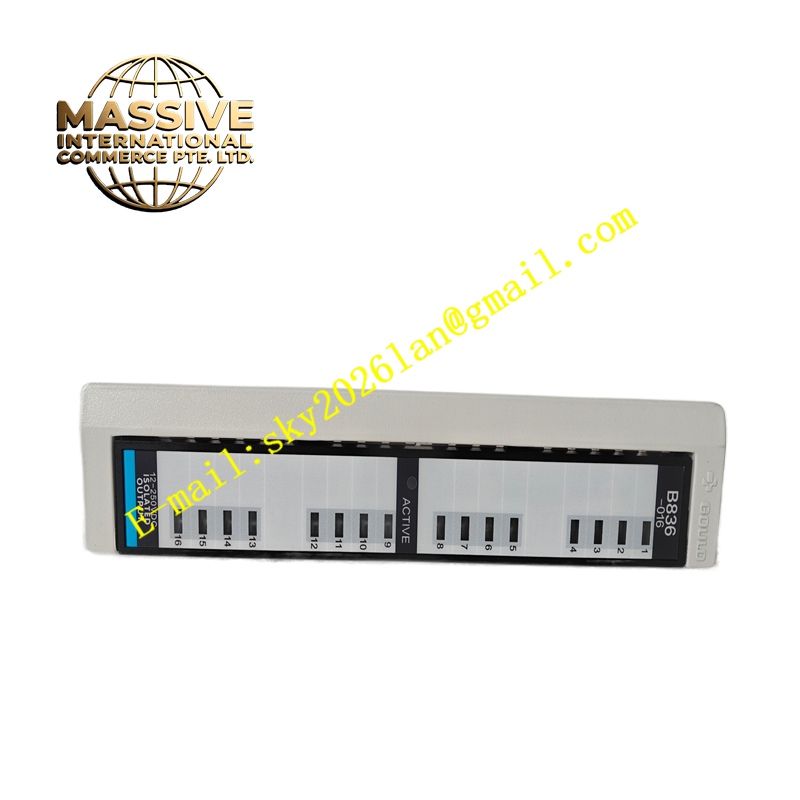
Description
Schneider AS-B836-016
Technical Specifications 16 digital output channels; output type is transistor sinking output; rated output voltage 24V DC; each channel equipped with overcurrent protection; opto-isolation between internal bus circuit and field output circuit; isolation withstand voltage 1500V AC; 24V DC field power supply; operating temperature 0°C to +60°C; IP20 protection rating.
Functional Features Receive digital output instructions from the rack main CPU through the backplane bus. Convert internal logic commands into 24V DC transistor switching signals for field actuators. Provide independent overcurrent protection for each output channel to prevent damage caused by short circuit. Upload channel fault status and diagnostic information to the CPU module. Support output force function used in engineering debugging.
Application Scenarios Automated assembly line actuator control, packaging machine solenoid valve control, material sorting equipment execution control, conveyor system auxiliary control, general factory discrete automation control.
Performance Parameters Fast channel response speed; independent per-channel short-circuit protection; low on-state voltage drop of output transistors; stable long-term switching operation.
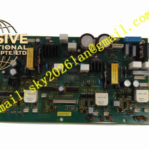
Material Composition Main PCB uses FR-4 flame-retardant multilayer printed circuit board; logic and drive chips are industrial semiconductors; optocoupler devices provide bus and field isolation; backplane gold finger contacts use gold-plated copper alloy; module housing is flame-retardant engineering plastic; terminal contact pieces use nickel-plated copper alloy.
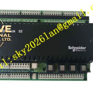
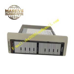
Structural Characteristics Vertical plug-in rack module for Schneider Modicon compatible racks. Front panel has LED status indicators for each output channel. Rear gold finger connector connects to rack backplane for bus communication and module power supply. Front screw terminal blocks are used for field actuator wiring. Side locking clip fixes the module in rack slots.
Working Principle The CPU module sends output state commands to this module through the backplane bus. The onboard logic circuit identifies command signals and controls the on and off state of each output transistor. 24V DC power supplies field actuators through transistor channels. The module monitors output current of each channel and reports short-circuit faults to the CPU immediately.
Installation Requirements Cut off rack power before installing or replacing the module. Insert the module into the designated rack slot and lock the retaining clip. Wire 24V DC field power and field actuators to module output terminals. Configure channel output parameters in supporting programming software. Test each channel switching function after power recovery.
Precautions for Use Do not connect inductive loads without freewheeling protection components to transistor outputs. Separate field output cables from analog signal cables. Take anti-static measures when touching bare circuit boards. Check terminal tightness regularly during equipment maintenance.