Description
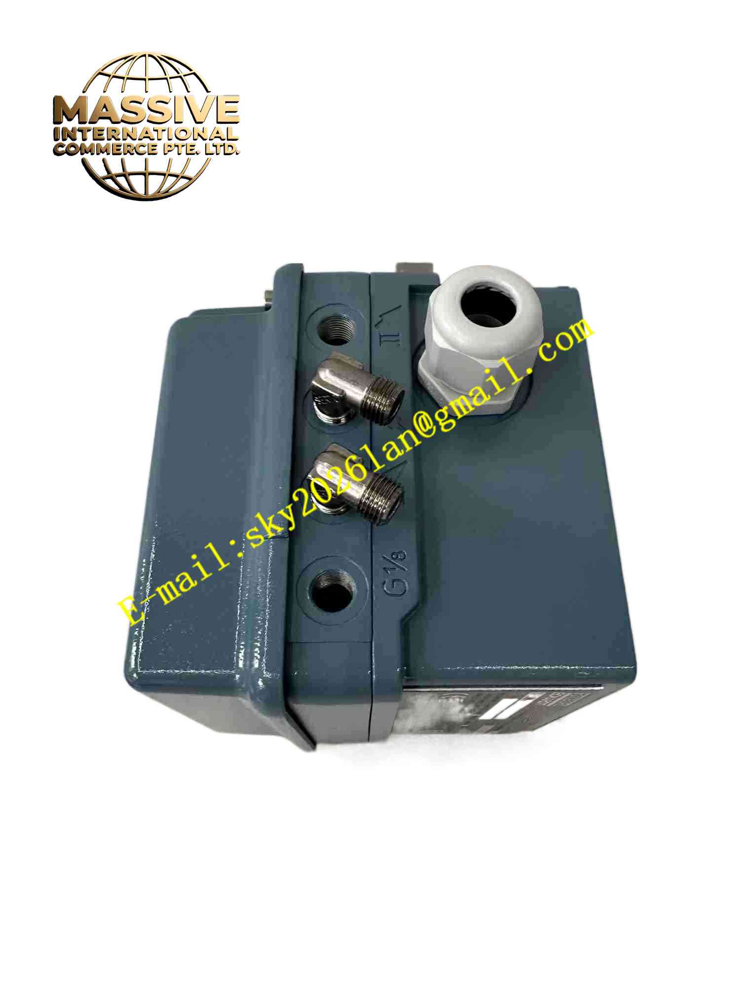
Schneider SRI986-BIDS7ZZZNA
Technical Specifications
Manufacturer: FOXBORO / ECKARDT, Schneider Electric
Part number: SRI986-BIDS7ZZZNA
Product type: electro-pneumatic valve positioner
Control signal: 4-20 mA DC, loop-powered
Pneumatic supply pressure: 1.4 to 6 bar
Actuator compatibility: single-acting and double-acting pneumatic actuators
Mounting standard: NAMUR / VDI/VDE compatible mounting
Enclosure protection: IP65
Ambient temperature: -40 °C to +80 °C
Explosion protection: ATEX, FM, CSA intrinsic safety approvals depending on variant
Electromagnetic compatibility: CE compliant
Communication: HART capability available on applicable SRI986 variants
Pneumatic connection: typically G1/8
Electrical connection: typically M20×1.5 or 1/2-14 NPT depending on configuration
Position feedback: optional mechanical position indicator or built-in position transmitter
Optional accessories: pneumatic booster, valve position switch, external pressure gauge set
Functional Features
Accurate conversion of 4-20 mA signal to pneumatic actuator position
Independent zero and span adjustment
Adjustable gain and damping for stable valve control
Support for split-range control up to three segments
Low air consumption design
Insensitive to multi-directional vibration
Suitable for linear and rotary actuators
Optional HART communication for configuration and diagnostics
Optional position feedback and limit switch functions
Rugged enclosure for outdoor and hazardous process areas
Application Scenarios
Oil and gas process control
Chemical and petrochemical plants
Power generation steam and feedwater systems
Pulp and paper process lines
Water and wastewater treatment
Pharmaceutical process utilities
Natural gas pipeline stations
Refinery valve control loops
High-temperature and high-pressure pipeline regulation
Retrofit of legacy pneumatic valve control systems
Performance Parameters
Control accuracy: high-precision valve positioning
Sensitivity: less than 0.1 percent of stroke range
Non-linearity: less than 0.4 percent of stroke range
Hysteresis: less than 0.3 percent of stroke range
Supply pressure influence: less than 0.1 percent per 1 bar
Temperature influence: less than 0.3 percent per 10 K
Vibration influence: less than 0.25 percent of stroke range within specified vibration limits
Response performance: fast positioning with adjustable damping
Reliability: industrial process-grade design
Environmental tolerance: -40 °C to +80 °C operating range
Material Composition
Aluminum alloy housing
Pneumatic nozzle-flapper or I-P converter assembly
Feedback linkage and cam mechanism
Potentiometer or position sensing element depending on configuration
Terminal block and electrical interface
Pneumatic tubing connections
Sealing gaskets and O-rings
Stainless steel or plated fasteners
Protective coating for corrosion resistance
Nameplate with SRI986-BIDS7ZZZNA identification
Structural Features
Compact industrial positioner housing
Front or side access for zero and span adjustment
Feedback lever for actuator position detection
Pneumatic output ports for single or double-acting actuators
NAMUR-style mounting interface
Mechanical position indicator option
Local adjustment screws for gain and damping
Sealed enclosure for IP65 protection
Robust terminal compartment for electrical wiring
Modular accessory mounting capability
Working Principle
The positioner receives a 4-20 mA signal from a DCS, PLC, or controller. It compares the commanded position with the actual valve position detected by the feedback mechanism. The internal pneumatic amplifier then adjusts the air pressure supplied to the actuator until the valve reaches the required position. Gain and damping settings help stabilize control and reduce oscillation caused by valve friction or process disturbances.
Installation Requirements
Mount the positioner on the actuator according to NAMUR or VDI/VDE standards
Verify single-acting or double-acting configuration before installation
Connect clean, dry instrument air within 1.4 to 6 bar
Wire the 4-20 mA loop with correct polarity
Ensure the feedback lever is correctly aligned with the actuator shaft
Check pneumatic tubing for leaks after installation
Confirm enclosure seals and cable entries are properly tightened
Set gain and damping to initial recommended values before commissioning
Usage Precautions
Use only clean, dry, oil-free instrument air
Confirm hazardous-area approvals before installing in explosive atmospheres
Do not exceed the rated supply pressure
Verify actuator travel direction and feedback linkage orientation
Adjust gain and damping carefully to avoid valve hunting
Keep the enclosure closed during operation to maintain IP65 protection
Perform periodic stroke checks and leak inspections
Refer to the official FOXBORO/ECKARDT SRI986 manual for exact wiring, calibration, and safety limits